
Belt and steel wire rope combined traction digitized energy-saving pumping unit

A technology of steel wire rope and pumping unit, which is applied in the field of beamless pumping unit, which can solve the problems of belt vibrating and shaking in case of wind, potential safety hazards, and stealing lubricating oil, etc., so as to eliminate leakage pollution, facilitate wellhead operations, reduce The effect of labor intensity

Inactive Publication Date: 2014-03-26
HENAN XINYU PETROLEUM MACHINERY MFG
View PDF10 Cites 4 Cited by
  • Summary
  • Abstract
  • Description
  • Claims
  • Application Information

AI Technical Summary

Problems solved by technology

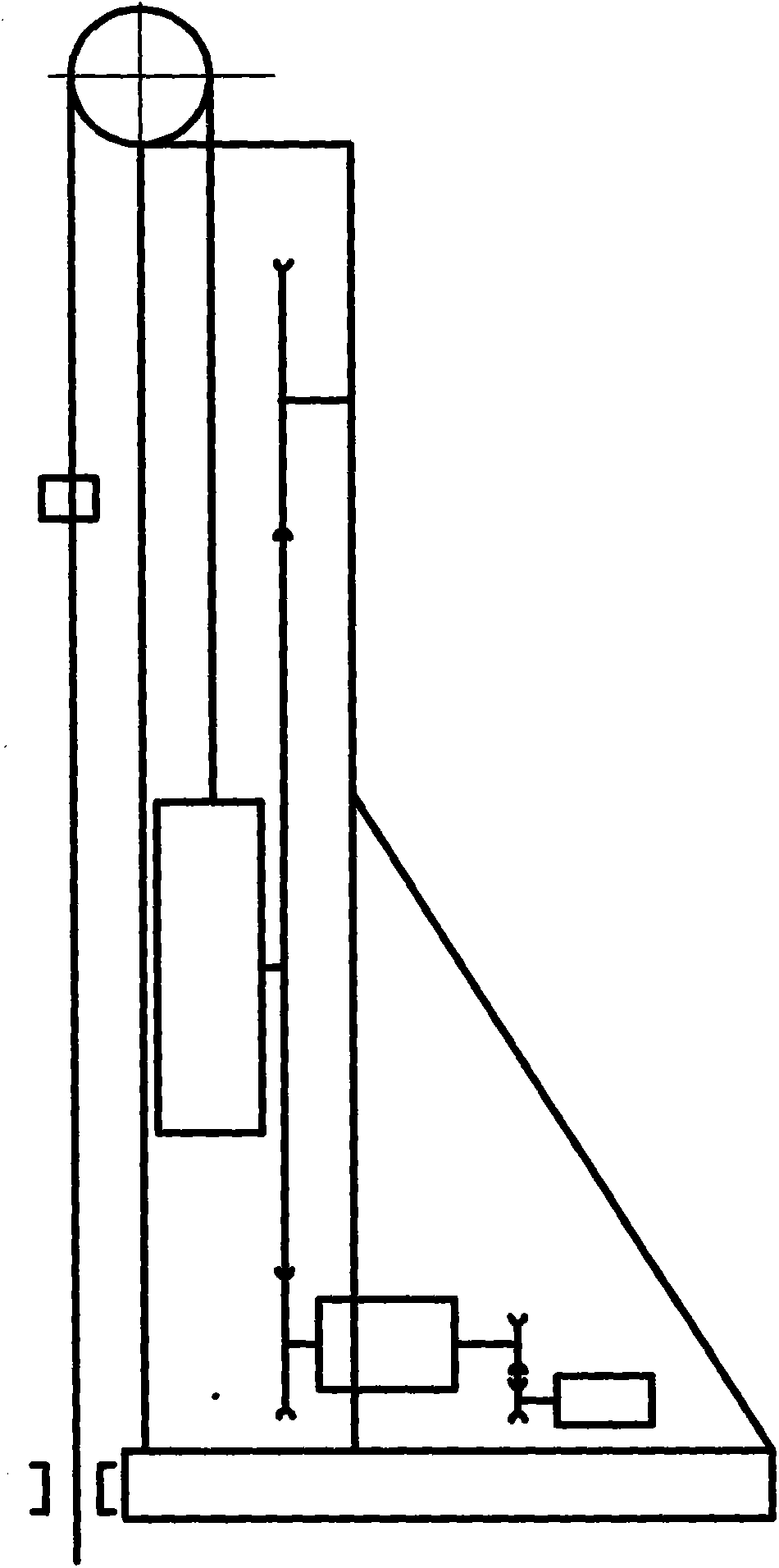
However, the power still uses the electric motor of the same specification as the beam pumping unit, and it still belongs to the big horse-drawn trolley
And there is a set of cumbersome mechanical reversing mechanism, which has low efficiency and high noise
The transmission mechanism still uses a gearbox, and the gearbox is placed on the ground, so it is easy for criminals to steal the lubricating oil. If the stolen lubricating oil is not found in time, it is easy to cause the bearing to burn, and eventually the gearbox will be scrapped.
In addition, the belt vibrates and vibrates in case of wind, which poses a potential safety hazard.
Wellhead operations need to move the whole machine backwards, which is inconvenient
Difficult maintenance in case of failure, high cost of the whole machine and other defects

Method used


Image

  • Belt and steel wire rope combined traction digitized energy-saving pumping unit
  • Belt and steel wire rope combined traction digitized energy-saving pumping unit
  • Belt and steel wire rope combined traction digitized energy-saving pumping unit

Examples


Embodiment Construction

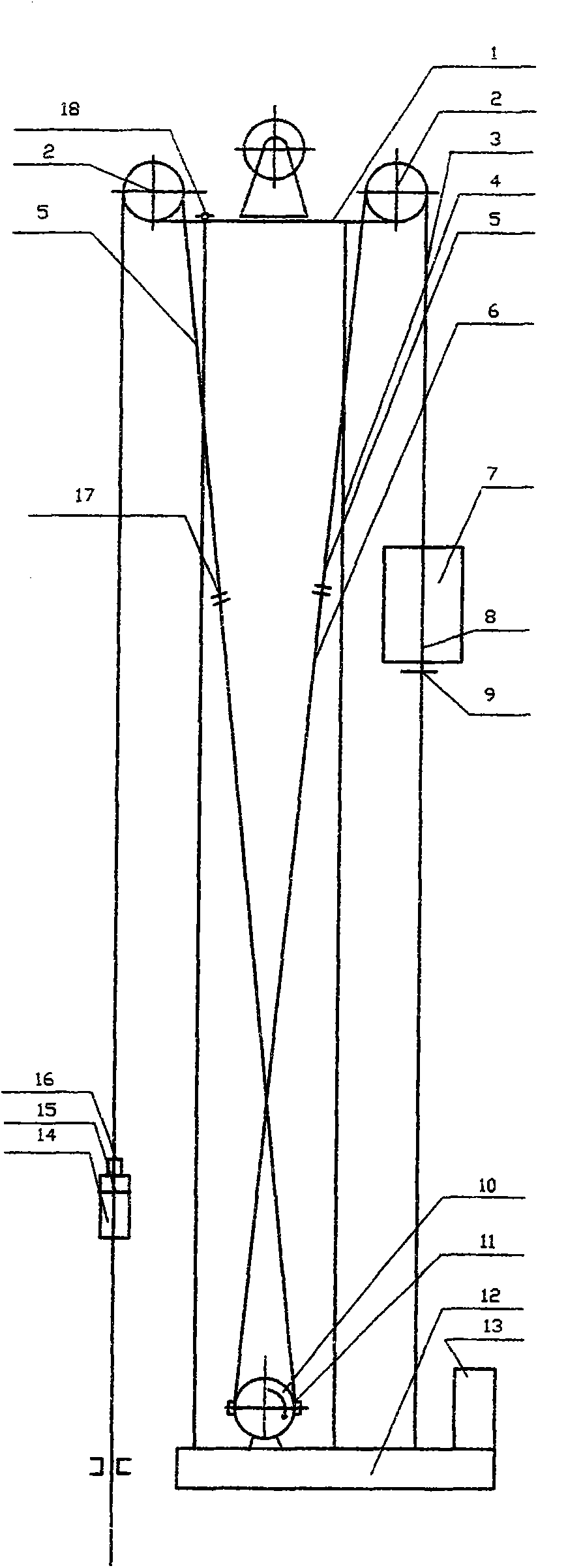
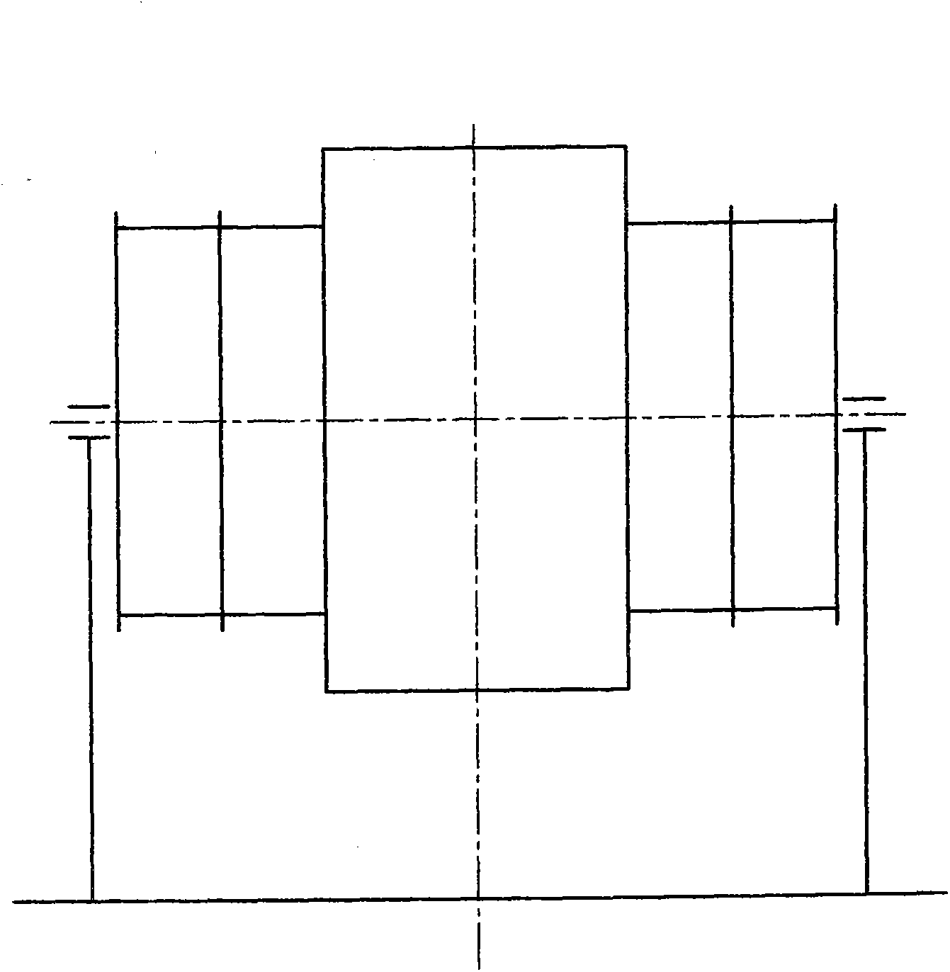
[0024] exist figure 2 Among the embodiments: 1. is the upper platform of the pumping unit, which is welded with section steel, and the upper platform 1 is the base of the fixed pulley 2, and it is installed on the frame 4. Frame 4 is the carrier of pumping unit, is made of section steel, and it is installed on the concrete foundation 12. The 2nd, fixed pulley, fixed pulley utilizes MC to make, and fixed pulley seat utilizes cast steel to make. image 3It is a structural diagram of the motor 10, and the motor is designed as a rare-earth permanent magnet synchronous motor with low speed and high torque of the outer rotor. The motor 10 is installed on the concrete foundation 12, and driving wheels are arranged on both sides of the motor 10 for power transmission by flexible cables. A brake system 11 is installed on the outer edge of the outer rotor of the motor 10 . The power of motor 10 is transmitted by belt, wire rope, fixed pulley. The 3rd is traction system, adopts belt...


PUM


Abstract

A belt and steel wire rope combined traction digitized energy-saving pumping unit is composed of a machine frame, an upper platform, a motor, a brake system, a traction system, a balance weight system, a control system, a safety mechanism and a folding abdicating mechanism. The motor is a low-rotating-speed high-torque rare-earth permanent magnet synchronous motor with an outer rotor, belt drive wheels are coaxial with the motor and arranged on the two sides of the motor, the lower end of a front belt and the lower end of a rear belt are in the opposite winding directions and wound on a motor drive wheel, the upper ends of the belts are connected with steel wire ropes through connecting devices, the other ends of the two steel wire ropes are connected with a suspension point load and a balance weight respectively, and therefore the traction system is obtained. The motor rotates forward and backward so that the pumping unit can reciprocate, the forward rotation and backward rotation of the motor and the running speed of the motor are controlled by the control system according to a digitized program, the brake system is arranged on the outer edge of the outer rotor of the motor, and the folding abdicating mechanism is arranged on the front side of the upper platform. The pumping unit saves energy, and is environmentally friendly, safe and reliable, and labor intensity of workers is lowered.

Description

technical field [0001] The invention relates to a pumping unit in oil field petroleum machinery, in particular to a beamless pumping unit in petroleum oil production machinery. Background technique [0002] Known pumping unit has beam pumping unit and beam pumping unit without beam at present. The former is a traditional pumping unit, which has been used for more than 100 years and has the advantages of being durable. However, the large horse-drawn trolley has a long transmission path, low mechanical efficiency, high energy consumption, and difficult parameter adjustment. It is not suitable for long-stroke and low-stroke occasions. The latter is the beamless pumping unit developed successively by relevant R&D personnel in combination with the actual situation of the oil field in the past ten years. At present, there is an intelligent wide-belt pumping unit (patent number: 200620085856.4) on the market. This pumping unit has long strokes and low stroke times, and is suitable...

Claims


Application Information

Patent Timeline
Patent Type & Authority Applications(China)
IPC IPC(8): E21B43/00
Inventor 廖启新王英军王献辉廖大林李要民董丽丽王会萍张明忠高利兵
Owner HENAN XINYU PETROLEUM MACHINERY MFG
Learn More