
Pollution-free heating tube device of vertical vacuum ion film plating machine

A heating tube, coating machine technology, applied in ion implantation coating, vacuum evaporation coating, sputtering coating and other directions, can solve the problem of secondary pollution, achieve compact equipment, solve secondary pollution problem, improve coating quality and work efficiency

Active Publication Date: 2014-04-02
DONGGUAN HUICHENG VACUUM TECH
View PDF4 Cites 3 Cited by
  • Summary
  • Abstract
  • Description
  • Claims
  • Application Information

AI Technical Summary

Problems solved by technology

[0006] The object of the present invention is to provide a vertical vacuum ion coating machine with simple and compact structure, capable of solving the secondary pollution problem caused by heating tubes, reliable in operation, time-saving and labor-saving, high in efficiency, and capable of reducing product defect rate and cost. Contamination heating pipe device

Method used


Image

  • Pollution-free heating tube device of vertical vacuum ion film plating machine
  • Pollution-free heating tube device of vertical vacuum ion film plating machine
  • Pollution-free heating tube device of vertical vacuum ion film plating machine

Examples


Embodiment 1

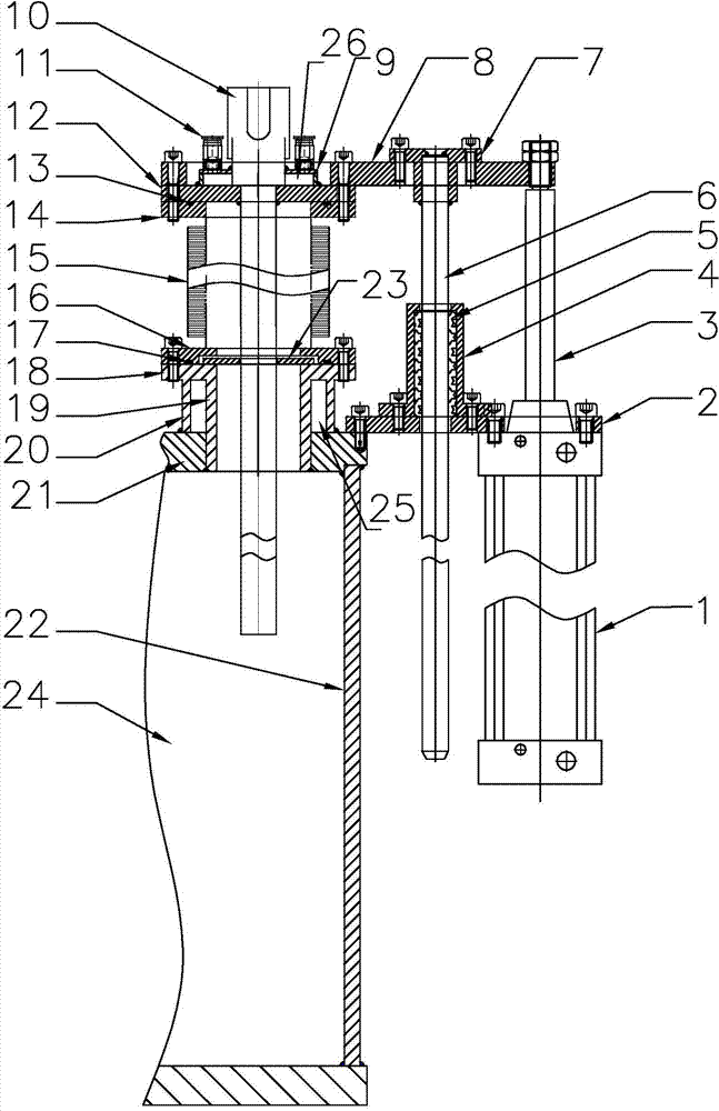
[0031] like figure 1 Shown is a pollution-free heating tube device for a vertical vacuum ion coating machine of the present invention, including a heating tube assembly, a bellows assembly, a bellows support seat assembly and a lifting mechanism. The heating tube assembly is composed of a special heating tube 10, a heating tube flange 12, a water cooling cover 9 at the end of the heating tube, and a water inlet and outlet nozzle 11. The upper end of the special heating tube 10 is the leading end of the wire, and the leading end is provided with an insulating joint. The position of the heating wire in the heating tube 10 is far from the leading end. When the heating tube 10 is lowered to the lowest position, the heating wire is located on the top plate 21 Slightly below, the top plate 21 of the furnace body is located at the upper end of the surrounding board 22 of the furnace body of the coating chamber 24 . The heating pipe flange 12 is attached to the shoulder of the heatin...

Embodiment 2

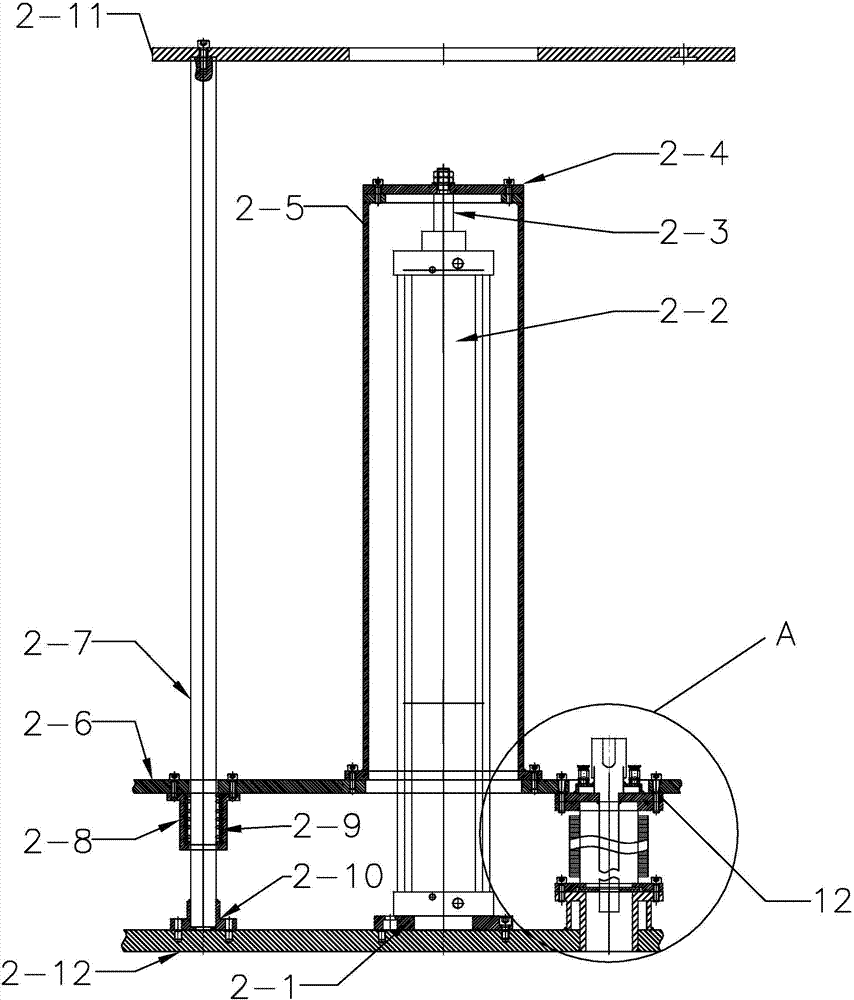
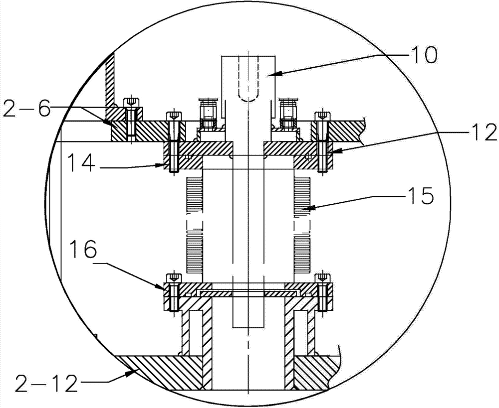
[0040] like figure 2 , 3 As shown, the difference between this embodiment and Embodiment 1 is that this embodiment is applied to a plurality of heating tubes to rise and fall simultaneously, and only one lifting mechanism is equipped, and the lifting mechanism includes a lifting plate 2-6, a cylinder 2-2 and a cylinder cover , The cylinder cover is composed of a support cylinder 2-5 and a support cylinder flange 2-4 located at the upper port of the support cylinder 2-5. Cylinder 2-2 is installed on the furnace body top plate 2-12 of coating chamber by cylinder fixed base 2-1, and the piston rod 2-3 of cylinder 2-2 stretches out upwards. The cylinder cover is covered on the cylinder 2-2, and the piston rod 2-3 is connected and fixed with the support tube flange 2-4 top surface of the cylinder cover. The lifting plate 2-6 is set on the lower part of the cylinder 2-2, the lower port of the support cylinder 2-5 is fixed on the lifting plate 2-6, and several mounting holes for t...


PUM


Abstract

The invention discloses a pollution-free heating tube device of a vertical vacuum ion film plating machine. The pollution-free heating tube device comprises a heating tube assembly, a corrugated tube assembly, a corrugated tube supporting seat assembly and a lifting mechanism, wherein the heating tube assembly comprises heating tubes, the upper ends of the heating tubes are insulating conducting wire lead-out ends, heating tube flanges are slightly below the heating tubes and are downwardly connected with the corrugated tube assembly, the corrugated tube assembly is downwardly connected with the corrugated tube supporting seat assembly, the corrugated tube supporting seat assembly is downwardly communicated with a furnace through heating tube access ports formed in a top plate of a furnace body, and the heating tubes penetrate through the hollow internal cavities of the corrugated tube assembly and corrugated tube supporting seat assembly, extend into the heating tube access ports in the top plate of the furnace body, enter the furnace and are connected with the lifting mechanism through the heating tube flanges. The heating tubes are not located in a film plating room during film plating, and then, plated layers cannot be attached and remained onto the heating tubes, so that the problem of secondary pollution caused by the heating tubes is solved; the pollution-free heating tube device has the advantages that the structure is simple and compact, and the work of heating tube cleaning is avoided, the quality of the plated layers is improved, the work efficiency is increased, and the production cost is reduced.

Description

technical field [0001] The invention relates to a vertical vacuum ion coating machine, in particular to a pollution-free heating tube device of the vertical vacuum ion coating machine. Background technique [0002] One of the main uses of the vacuum ion coating machine is to coat decorative films. Most of the ion-plating decorative films use transition metal targets, such as Ti, Zr, and Cr. Metal plasma is generated by cathodic arc or magnetron sputtering. Nitrogen, acetylene and oxygen react to synthesize nitrides, carbides, nitrogen carbides and oxides, etc., to obtain decorative films such as gold, rose gold, black, coffee, brown, silver white, blue, etc., which are both wear-resistant and Corrosion resistance, currently widely used in watch parts, mobile phone cases, accessories, golf equipment, sanitary ware, hardware, metal furniture, hotel appliances, stainless steel decorative plates, etc.; various color decorative films are plated on it, Play a colorful effect. ...

Claims


Application Information

Patent Timeline
IPC IPC(8): C23C14/22
Inventor 李志荣李志方罗志明袁镇海李秋霞
Owner DONGGUAN HUICHENG VACUUM TECH
Learn More