In-well drill-following navigation method based on magnetic detection

A navigation method and magnetic detection technology, applied in drilling equipment, earth-moving drilling, automatic control system of drilling, etc., can solve the problems of weak magnetic field strength of permanent magnet short joints, limited distance of magnetic detection and navigation, complicated calculation method, etc. To achieve the effect of simple method, reduced loss and time, and high navigation accuracy

Inactive Publication Date: 2014-04-02
CHINA UNIV OF GEOSCIENCES (WUHAN)
View PDF11 Cites 13 Cited by
  • Summary
  • Abstract
  • Description
  • Claims
  • Application Information

AI Technical Summary

Problems solved by technology

In recent years, the domestic research on underground magnetic navigation in my country is mainly to realize short-distance twin-well connected mining. For example, the Nanchang Hangkong University’s application for "an underground magnetic navigation method" was published in 2011, which fixes the permanent magnet short joint on the drill bit. The magnetic signal is sent out at one end, and the magnetic vector sensor is placed in the other shaft to receive the magnetic signal from the permanent magnet joint. The disadvantage is that the magnetic field intensity emitted by the permanent magnet joint is weak, which limits the distance of magnetic detection and navigation. It also limits its application in strong magnetic geological conditions; at the same time, it fixes the permanent magnet short joint at the drill bit end, causing the detected signal coordinates to be dynamic, thus complicating the calculation method

Method used


Image

  • In-well drill-following navigation method based on magnetic detection
  • In-well drill-following navigation method based on magnetic detection
  • In-well drill-following navigation method based on magnetic detection

Examples


Embodiment 1

[0043] Embodiment 1: the present invention provides a kind of navigation method while drilling in the well based on magnetic detection, operate according to the following steps:

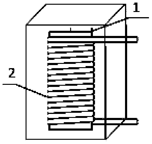
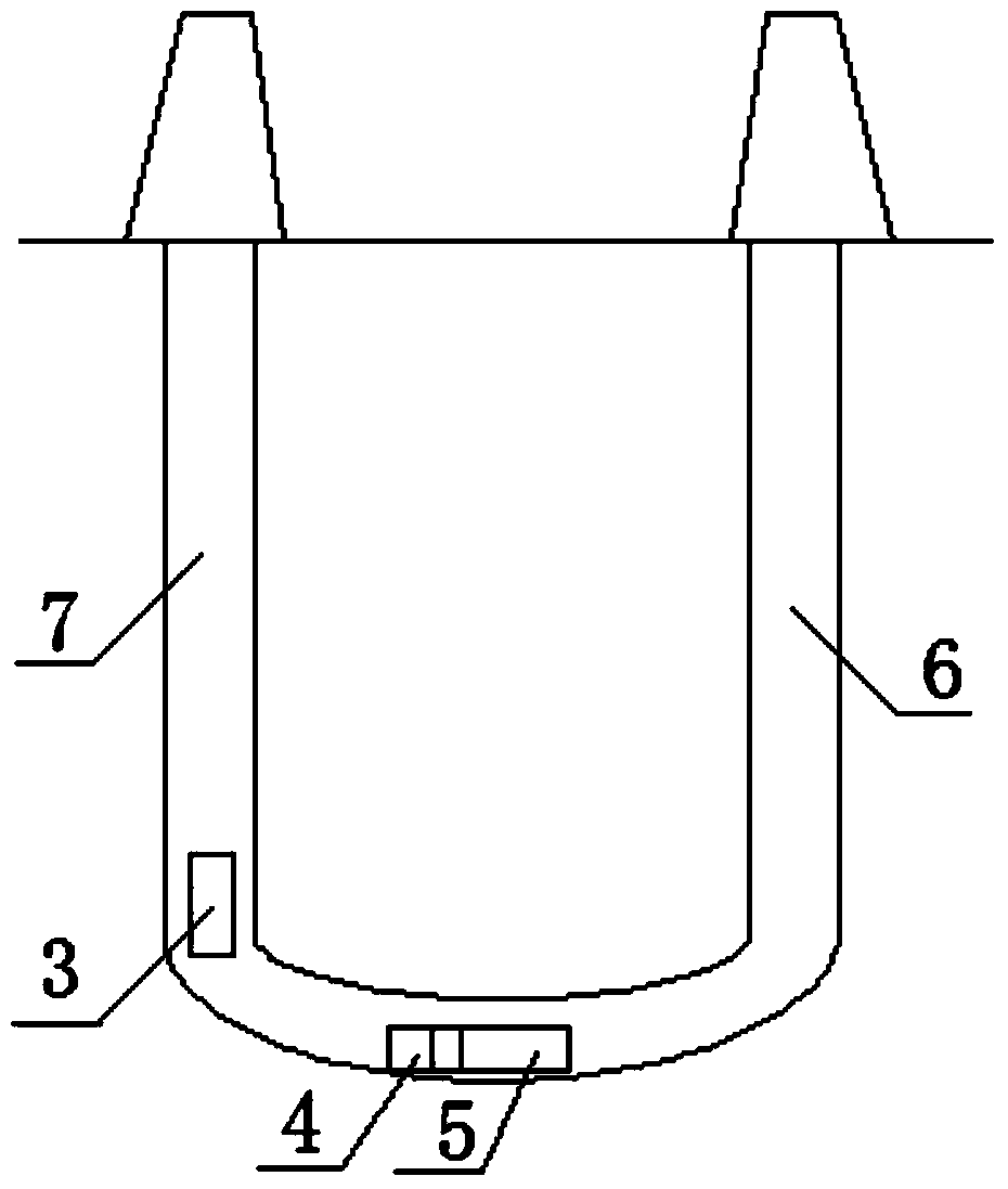
[0044] Step 1. Drill two vertical wells respectively. For the detection well 6 and the target well 7, fix the magnetic vector detector 5 on the end of the drill bit 4, put it into the bottom of the detection well 6, put the artificial magnetic source 3 into the bottom of the target well 7, The detection well 6 and the target well 7 are two vertical wells with a depth of 1000 meters and a distance of 200 meters between the two wells. Such as figure 2 shown. The artificial magnetic source is composed of a coil 2 wound on a strip ferromagnet 1, such as figure 1 shown. The number of turns n of the artificial magnetic source is 1000, and the radius R is 0.1 meters. The magnetic vector detector 5 adopts a Mag611 high-temperature three-axis fluxgate probe, which can have 4 fixing holes through the magn...


PUM


Abstract

The invention relates to an in-well drill-following navigation method based on magnetic detection. The method comprises the following steps: firstly, fixing and putting a magnetic vector detector and a drill bit into the bottom of a detected well, and putting an artificial magnetic source into the bottom of a target well; powering on the artificial magnetic source to generate an induced magnetic field, and adjusting the current to enable the magnetic vector detector in the detected well to receive a magnetic sensing signal; transmitting the received signal to a ground computer through the detector, calculating the distance, the horizontal deflection and the vertical deflection of the drill bit relative to the artificial magnetic source under a spherical coordinate system through the computer according to the magnetic sensing strength, drawing a planar projection drawing of the drill bit, and displaying central deviation; and furthermore adjusting the drilling direction of the drill bit according to the deviation and the angle so as to enable the drill bit to move forwards to the artificial magnetic source. The deviation and the angle are measured and calculated every 2-10 minutes in the drilling process, and the direction of the drill bit is adjusted at any time so as to ultimately communicate a horizontal well with a vertical well. Due to adoption of the artificial magnetic source, the method is large in navigation distance, simple in calculation method and high in precision, and the direction can be measured along with drilling.

Description

technical field [0001] The invention relates to a navigation-while-drilling method in a well based on magnetic detection, in particular to a navigation-while-drilling method in which a horizontal well communicates with two vertical wells. Background technique [0002] Artificial magnetic navigation technology began to rise in the United States in the 1980s. After decades of development, this technology has been widely used in the geological survey industry. For example, in the mining of water-soluble solid minerals, the use of U-shaped drilling has a small footprint and is environmentally friendly and clean. gas explosion accident. In addition, directional drilling technology is involved in deep prospecting, geothermal engineering and oil extraction. my country's artificial magnetic navigation technology is in its infancy. The existing dozens of wells in China rely on foreign drilling technology service companies, and the service fees are expensive. Therefore, it is immine...

Claims


Application Information

Patent Timeline
IPC IPC(8): E21B44/00E21B47/13
Inventor 韩骑胡祥云周晓权刘双
Owner CHINA UNIV OF GEOSCIENCES (WUHAN)
Why Eureka
Try Eureka