Single crystal furnace capable of improving czochralski-method single crystal growth speed

A growth rate and single crystal furnace technology, which is applied in the field of single crystal furnaces to increase the growth rate of Czochralski single crystals, can solve the problems of increasing heater power, increasing labor intensity of production workers, and easy splashing of silicon melt, etc., to reduce Effect of heater power, reduction of heat loss, and ease of cleaning and charging

Inactive Publication Date: 2014-04-09
SHANGHAI YONGZHEN MACHINERY +1
View PDF18 Cites 11 Cited by
  • Summary
  • Abstract
  • Description
  • Claims
  • Application Information

AI Technical Summary

Problems solved by technology

However, the cooler is placed close to the inner side of the heat shield. While taking away the heat lost by the single crystal, it also takes away the heat of the heat shield, which increases the power required by the heater to maintain the crystal growth. The lower end of the cooler has no shield protection, and the silicon m

Method used


Image

  • Single crystal furnace capable of improving czochralski-method single crystal growth speed
  • Single crystal furnace capable of improving czochralski-method single crystal growth speed
  • Single crystal furnace capable of improving czochralski-method single crystal growth speed

Examples


Embodiment 1

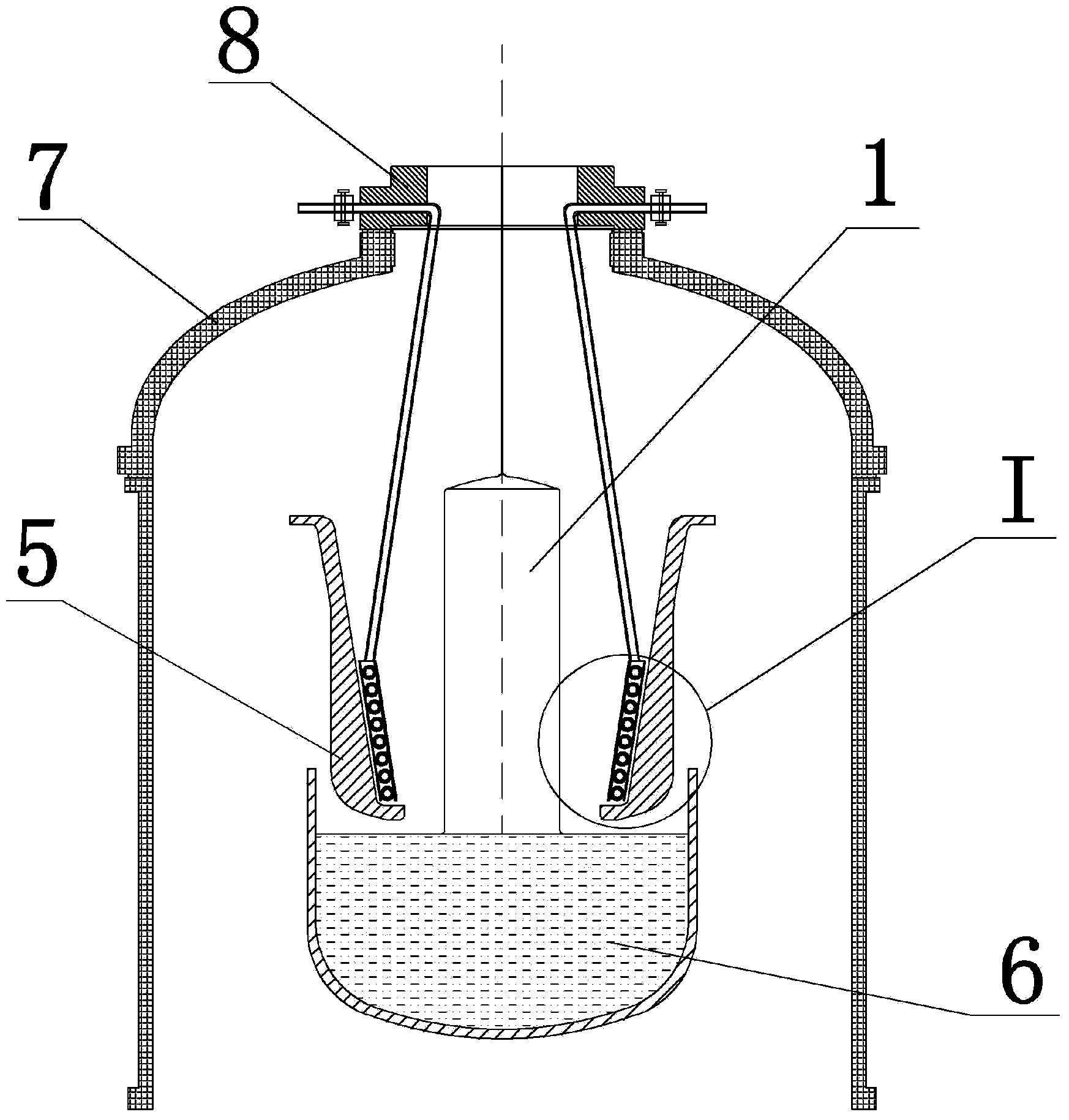
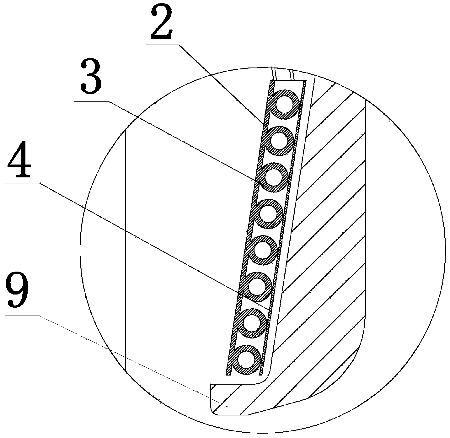
[0043] like figure 1 and figure 2 As shown, this embodiment is a single crystal furnace for improving the growth rate of Czochralski method single crystal, which includes a guide tube, and a cooling device is arranged in the guide tube, and the cooling device is composed of three-layer components with a taper , the outermost layer is a molybdenum cylinder 4, the middle layer is a hollow wound copper tube 3 with internal cooling water (the cooling medium includes but not limited to water, and other cooling fluids such as argon or helium), and the innermost layer is Copper cylinder 2. The gap between the inner side of the molybdenum cylinder 4 and the wound copper pipe 3 is 0-30 mm, and the gap between the outer side of the molybdenum cylinder 4 and the guide tube 5 is 0-30 mm. The coiled copper pipe 3 through which cooling water is passed inside has a taper of 0° to 80°, such as Figure 5 As shown, it is wound in a spiral shape. After winding, it passes out of the furnace ...

Embodiment 2

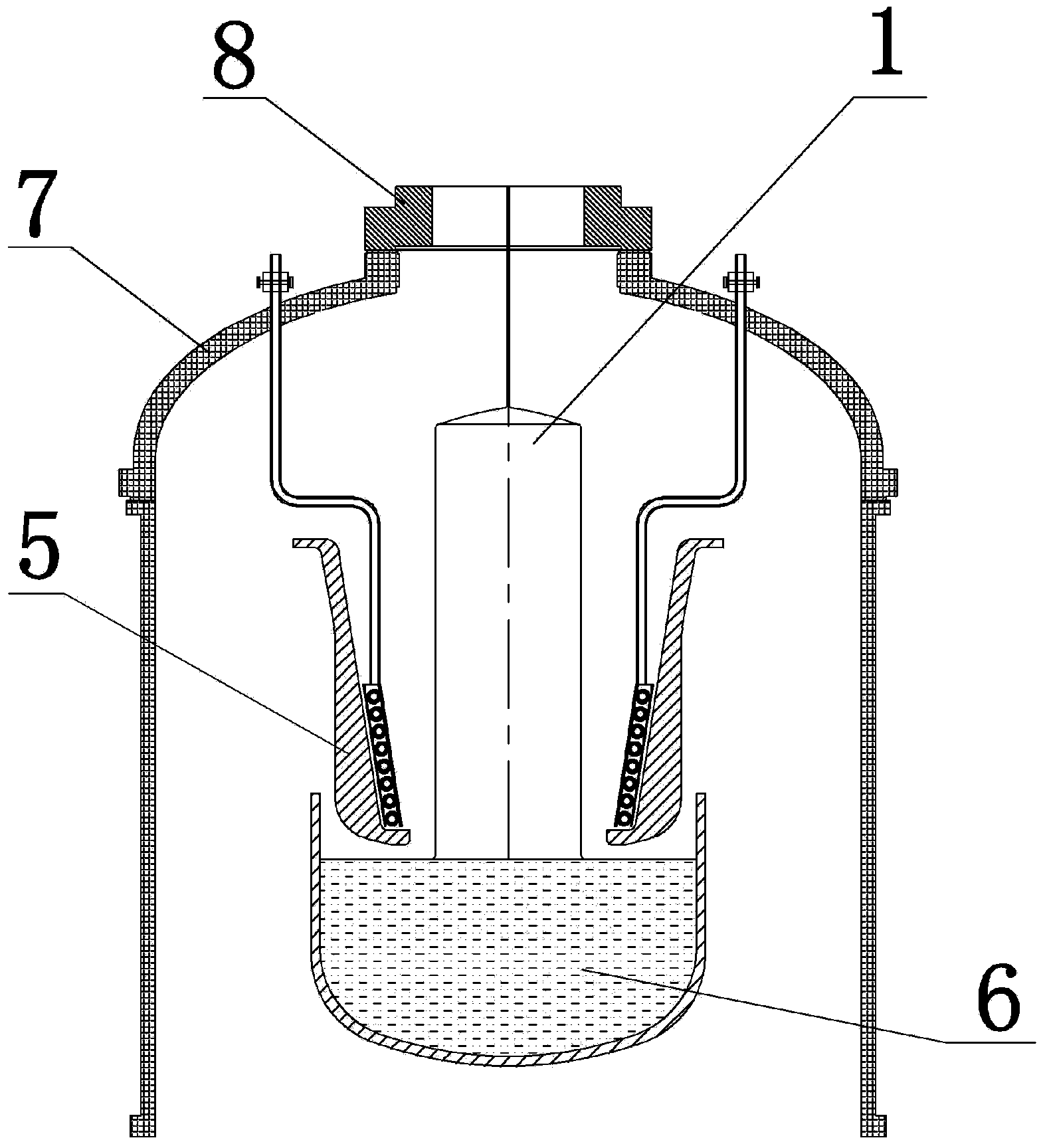
[0046] like image 3 As shown, there is another way for the wound copper tube 3 of the cooling device in the single crystal furnace in this embodiment to pass out of the single crystal furnace. The coiled copper pipe 3 through which the cooling water flows inside is wound in a spiral shape, and passes out of the furnace cover 7 of the single crystal furnace after winding, and is then connected with the cooling water inlet and outlet pipelines of the furnace platform equipment. All the other parts are identical with embodiment 1.

Embodiment 3

[0048] like Figure 4 As shown, the outermost layer of the cooling device in the single crystal furnace in this embodiment is a molybdenum cylinder 4, the middle layer is a copper cylinder 2, and the innermost layer is a wound copper tube 3 through which cooling water passes. The gap between the inside of the molybdenum cylinder 4 and the copper cylinder 2 is 0-30 mm, and the gap between the outside of the molybdenum cylinder 4 and the guide tube 5 is 0-30 mm. The coiled copper pipe 3 through which cooling water is passed inside has a taper of 0° to 80°, such as Figure 5 As shown, it is wound in a spiral shape, and after winding, it is passed out of the furnace from the furnace cover connecting flange 8 or furnace cover 7 of the single crystal furnace, and then connected to the cooling water inlet and outlet pipelines of the furnace platform equipment. There is sufficient surface contact between the wound copper tube 3 and the copper cylinder 2, the cross section of the wound...


PUM

PropertyMeasurementUnit
Thermal conductivityaaaaaaaaaa

Abstract

The invention discloses a single crystal furnace capable of improving a czochralski-method single crystal growth speed. The single crystal furnace comprises a draft tube, wherein a cooling device is arranged in the guide cylinder; the cooling device comprises a molybdenum cylinder encircling along the inner wall of the guide cylinder; a hollow copper tube is arranged in an encircling manner at the inner side of the molybdenum cylinder; the two ends of the copper tube extend to the outside of the single crystal furnace, and one end of the copper tube serves as an inlet for a cooling medium while the other end of the same serves as an outlet for the cooling medium; and the copper tube is full of the flowing cooling medium. Besides, a copper cylinder is connected at the inner side of the copper tube. The single crystal furnace is reasonable in structural design; the copper tube penetrates to the outside of the single crystal furnace after being wound by a certain taper; and therefore, the possibility of leakage of the cooling medium in the furnace is avoided. The guide cylinder is capable of preventing the melt from splashing to the cooling device. The device is adopted in the thermal field of the czochralski-method single crystal furnace so that the crystal cooling effect near the growth interface can be strengthened and the longitudinal temperature gradient of crystals can be increased; and as a result, the growth speed of crystals can be greatly increased. Besides, the purposes of quickly growing crystals and reducing the crystal processing cost are achieved.

Description

technical field [0001] The invention relates to a single crystal furnace in the field of Czochralski method single crystal growth, in particular to a single crystal furnace for improving the growth rate of Czochralski method single crystal. Background technique [0002] In the Czochralski method of single crystal growth, the raw materials and dopants are first melted in the crucible, and then a single crystal with a certain crystal orientation is used as the seed crystal, which is inserted into the melt from the upper part, and gradually Pull upward with a certain diameter, and then make the melt grow into a single crystal at a certain speed with the seed crystal as the seed. [0003] From the perspective of heat balance, the growth rate formula of a single crystal can be deduced as: [0004] VpHA=K S G S -K L G L (1) [0005] Among them: V-single crystal growth rate; [0006] p - single crystal density; [0007] H - the latent heat of crystallization of the mel...

Claims


Application Information

Patent Timeline
IPC IPC(8): C30B15/00
Inventor 吴亮黄小卫孟召标刘辉伍耀川陈龙
Owner SHANGHAI YONGZHEN MACHINERY
Why Eureka
Try Eureka