Thermal power unit sliding pressure optimizing and regulating system and method

A technology for thermal power units and regulating systems, applied in electrical program control, program control in sequence/logic controllers, etc., can solve problems such as difficulty in sliding pressure curve, discount of optimization results, and reduction of energy storage level, and achieve optimal sliding pressure. The effect of operating pressure, improving load economy and reducing throttling loss

Active Publication Date: 2014-04-09
XIAN TPRI THERMAL CONTROL TECH +1
View PDF6 Cites 18 Cited by
  • Summary
  • Abstract
  • Description
  • Claims
  • Application Information

AI Technical Summary

Problems solved by technology

[0005] 1. The determination of the optimization curve depends on high-precision calculations and experiments on the operating economy of the entire power station, which requires more manpower and equipment resources, and the implementation cost is high
[0006] 2. The calculation result of the optimal sliding pressure operation curve tends to adopt a lower main steam pressure at a lower load, which will inevitably reduce the energy storage level of the unit under lower load conditions to a large extent , resulting in a significant drop in the unit's primary frequency regulation and AGC load regulation capabilities
In order to meet the requirements of grid-connected power generation of generator sets, it is necessary to ensure the adjustment ability of primary frequency regulation and AGC. Therefore, the sliding pressure operation curve finally set by the actual unit often floats up the theoretically calculated optimal sliding pressure curve to improve the unit’s performance. The actual operating main steam pressure greatly discounts the relevant optimization results
[0007] 3. The theoretical optimal sliding pressure operation curve is not unique, and it changes with the changes of parameters such as ambient pressure, circulating water temperature, and unit back

Method used


Image

  • Thermal power unit sliding pressure optimizing and regulating system and method
  • Thermal power unit sliding pressure optimizing and regulating system and method

Examples


Embodiment Construction

[0023] The present invention will be described in more detail below in conjunction with the accompanying drawings and specific embodiments.

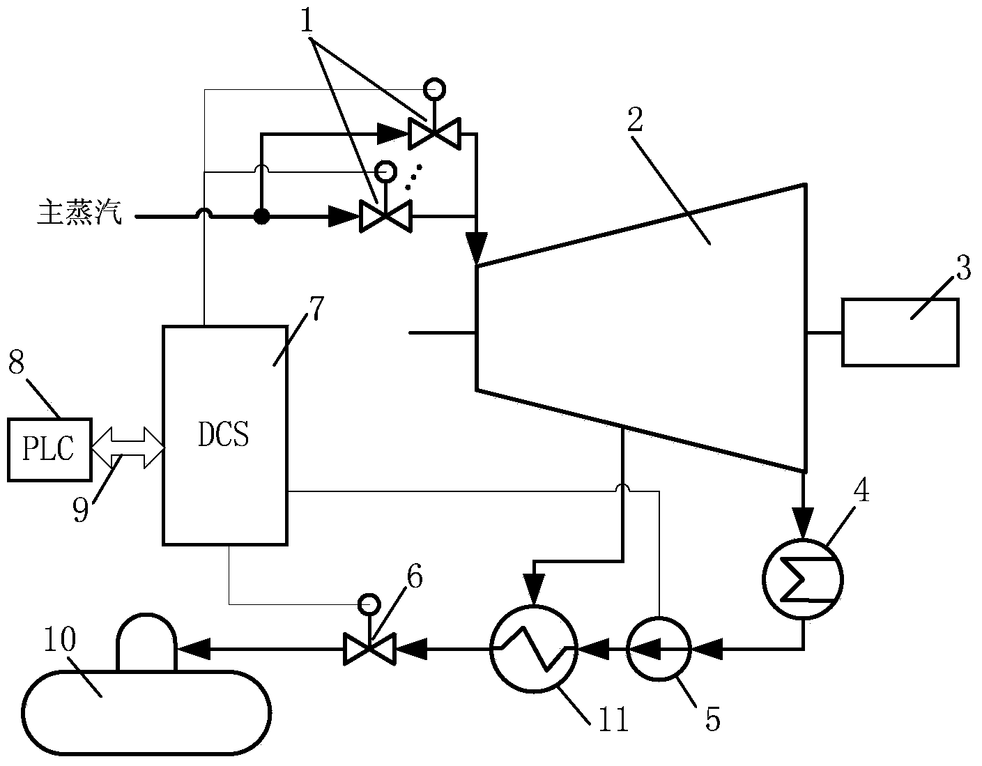
[0024] Such as figure 1As shown, the main steam from the boiler enters the steam turbine 2 through multiple steam turbine high-pressure regulating valves 1 to do work and drives the generator 3 to generate electric energy. The steam that has done work leaves the steam turbine 2 and enters the condenser 4 to condense into liquid condensate, which is sent to the deaerator 10 by the frequency conversion condensate pump 5 through multiple low-pressure heaters 11 and the deaerator water level regulating valve 6 . Part of the steam is extracted from the steam turbine 2, and the condensed water is heated in the low-pressure heater 11 to realize the heat recovery effect. The thermal power unit sliding pressure optimization adjustment system of the present invention includes a PLC control unit 8, a decentralized control system 7 connected to the...


PUM


Abstract

The invention discloses a thermal power unit sliding pressure optimizing and regulating system and method. The system comprises a PLC control unit, a distributed control system, a plurality of steam turbine septum valves, a variable-frequency condensate pump and a deaerator level control valve, wherein the distributed control system is connected with the PLC control unit through a two-way interface, the steam turbine septum valves are connected with the distributed control system, and the PLC control unit is used for achieving system parameter and signal reading through the distributed control system and achieving control over main steam pressure, the variable-frequency condensate pump and the deaerator level control valve. By means of the thermal power unit sliding pressure optimizing and regulating system and method, time-consuming and labor-consuming unit operation optimizing experiments and calculation are avoided, a set target of the main steam pressure can be dynamically optimized in real time according to environment changes, contradiction between main steam pressure optimizing capacity and load regulating capacity is avoided through the energy storage and regulation function of a condensate system, and the maximization of operating economy of a generator unit is dynamically achieved in real time under the premise that requirements of a power grid are met.

Description

technical field [0001] The invention relates to the technical field of thermal power generation unit control, in particular to a thermal power unit sliding pressure optimization adjustment system and an adjustment method. Background technique [0002] The actual operating energy consumption of thermal power units in my country is generally much lower than the design energy consumption of the units. On the one hand, long-term operation under partial load conditions makes the operating conditions of the units seriously deviate from the most economical design conditions; on the other hand, my country's relatively high The peak-to-valley ratio of power consumption makes the power grid require most units to participate in load regulation, retaining the ability to quickly raise and lower loads, and further sacrificing the operating economy of the units. [0003] The typical unit adjustment operation mode can be divided into two types: constant pressure operation and sliding pressur...

Claims


Application Information

Patent Timeline
IPC IPC(8): G05B19/05
Inventor 高林高海东薛建中王春利金国强肖勇孙德良
Owner XIAN TPRI THERMAL CONTROL TECH
Why Eureka
Try Eureka