Continuous flash process equipment for waste oil

A process equipment and flash evaporation technology, applied in the petroleum industry, hydrocarbon distillation, etc., can solve the problems of unstable chemical properties of oil products, endangering the safety of operators, and large loss of economic benefits, achieving the elimination of secondary pollution and a high degree of automation. , the effect of fast flash evaporation

Inactive Publication Date: 2014-04-16
SHANGQIU TENGLONG ENVIRONMENTAL PROTECTION EQUIP
View PDF4 Cites 4 Cited by
  • Summary
  • Abstract
  • Description
  • Claims
  • Application Information

AI Technical Summary

Problems solved by technology

[0002] The technology of thermally cracking waste tires and waste plastics to treat solid waste and recycle oil products has been rapidly promoted around the world. It not only eliminates the pollution of some solid waste to the environment, but also realizes the recycling of energy. Most of the crude oil and waste engine oil produced by pyrolysis of tires and waste plastics are used as thermal fuels. Because carbon black is produced during the pyrolysis process, the carbon black enters the condensation system along with the oil gas, so the color of the oil is relatively black. Magazine There are many, and the calorific value is not high, and the utilization rate is low; while a small number of simple distillation technology is used for simple treatment of oil products. Unstable, easy to be oxidized, resulting in blackening of oil color, serious impurities, and large loss of economic benefits
In the simple distillation process, it is inevitable to produce oil residue, which endangers the safety of operators and causes secondary pollution to the environment

Method used


Image

  • Continuous flash process equipment for waste oil
  • Continuous flash process equipment for waste oil
  • Continuous flash process equipment for waste oil

Examples


Embodiment Construction

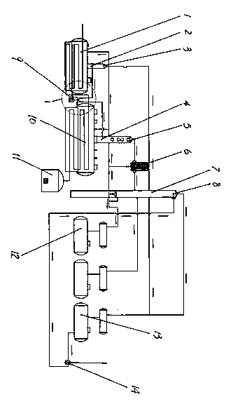
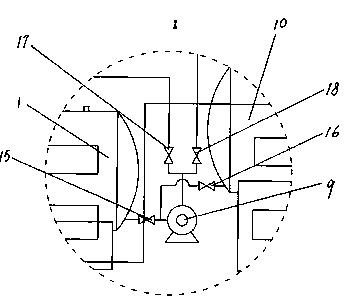
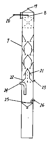
[0009] as attached figure 1 As shown, the process equipment is mainly composed of a hot blast stove 11, a preheating kettle 1, a gas collecting tower 3, a flash kettle 10, a flash tower 5, a fractionating tower 7, a condenser and each oil tank 12, 13. An oil pump 9 is installed between the kettle 1 and the flash kettle 10. The inlet of the oil pump 9 has a three-way connection. One end is connected to the bottom of the preheating kettle 1 through a valve 15, and the other end is connected to the bottom of the flash kettle 10 through a valve 16. The oil pump 9. The outlet is connected to a tee, and connected to the bottom of the gas collecting tower 3 above the preheating kettle 1 and the bottom of the flash tower 5 above the flash kettle 10 through connecting pipes, and valves 17 and 18 are respectively installed on the connecting pipes; The pipes at the bottom of the gas collecting tower 3 and the bottom of the flash tower 5 are inserted into the bottom of the tower, and the ...


PUM


Abstract

The invention provides continuous flash process equipment for waste oil. The continuous flash process equipment comprises a hot-blast stove, a preheating kettle, a gas collection column, a flash kettle, a flash column, a fractionating column, etc.; an oil pump is mounted between the preheating kettle and the flash column; a tee joint is arranged at an inlet of the oil pump, wherein one end of the tee joint is connected to the bottom part of the preheating kettle through a valve, while the other end of the tee joint is connected with the bottom part of the flash kettle through another valve; another tee joint connected to an outlet of the oil pump is respectively connected to the bottom part of the gas collection column above the preheating kettle and the bottom part of the flash column above the flash kettle through connecting pipes; the outlet in the top part of the flash column is connected to the middle part of the exposed fractionating column through an oil stopper; a diesel tank, the preheating kettle and the flash kettle are connected to the bottom part of the oil stopper through the pipelines. The continuous flash process equipment for waste oil is convenient to operate, high in degree of automation, high in processing precision, fast in flash speed, no any fuel, and high in output, and saves fuel; the produced oil has technical index and additional value higher than those produced by common distillation way; the produced oil can replace the raw material of a large ship oil plant and the crude oil of base oil, so that the economic benefit is great, and the resource and energy are saved.

Description

technical field [0001] The invention relates to a device for processing waste engine oil, tire oil, plastic oil and shale oil to obtain more pure oil products through a flash evaporation process. Background technique [0002] The technology of thermally cracking waste tires and waste plastics to treat solid waste and recycle oil products has been rapidly promoted around the world. It not only eliminates the pollution of some solid waste to the environment, but also realizes the recycling of energy. Most of the crude oil and waste engine oil produced by pyrolysis of tires and waste plastics are used as thermal fuels. Because carbon black is produced during the pyrolysis process, the carbon black enters the condensation system along with the oil gas, so the color of the oil is relatively black. Magazine There are many, and the calorific value is not high, and the utilization rate is low; while a small number of simple distillation technology is used for simple treatment of oil...

Claims


Application Information

Patent Timeline
Patent Type & Authority Applications(China)
IPC IPC(8): C10G7/00
Inventor 高峰
Owner SHANGQIU TENGLONG ENVIRONMENTAL PROTECTION EQUIP
Why Eureka
Try Eureka