Check patentability & draft patents in minutes with Patsnap Eureka AI!

Current equalizing circuit for power output and application thereof

A power supply output, input and output circuit technology, applied in the circuit field, can solve the problems of affecting the service life of the power supply, poor power supply flow rate, large heat loss, etc., to achieve low power consumption, high output flow rate, and reduce loss.

Inactive Publication Date: 2014-04-16
SHANGHAI MUNICIPAL ELECTRIC POWER CO
View PDF6 Cites 9 Cited by
  • Summary
  • Abstract
  • Description
  • Claims
  • Application Information

AI Technical Summary

Problems solved by technology

[0010] In order to solve the problems existing in the power supply current sharing method in the prior art, such as complicated control, excessive heat loss, poor current sharing degree of each power supply, affecting the service life of the power supply and being very cumbersome, troublesome debugging and slow response, the present invention provides A new type of current sharing circuit for power supply output and its application, after redesigning the circuit structure, it has obtained the controllable output current sharing degree, eliminated the error and drift caused by factors such as temperature and other factors, and the output is uniform Higher fluidity is beneficial to improve working life and reliability, while lower power consumption is beneficial to reduce heating rate and improve efficiency

Method used


Image

  • Current equalizing circuit for power output and application thereof
  • Current equalizing circuit for power output and application thereof
  • Current equalizing circuit for power output and application thereof

Examples


Embodiment

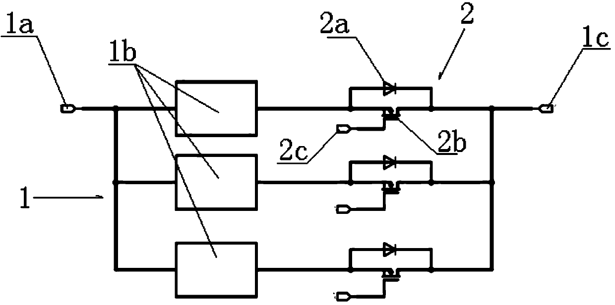
[0041] Metal Oxygen Half Field Effect Transistor 2b (the abbreviation MOSFET is used hereinafter), the function of loading this MOSFET is to replace the uncontrollable component diode for current sharing, so as to realize the control and adjustment of the output current sharing circuit. Since the MOSFET is a controllable power component, it can work in the linear region, saturation region, and cut-off region, specifically:

[0042] 1. When the driving voltage is high, the MOSFET can be regarded as a resistor with a small resistance;

[0043] 2. When the driving voltage is between the driving threshold voltage Vgs(th) and the full turn-on voltage value, the on-resistance of the MOSFET is proportional to the driving voltage, and the MOSFET can be regarded as a variable resistor at this time.

[0044] 3. If figure 2As shown, when the circuit is working, the voltage drop on the on-resistance of the MOSFET is much smaller than the forward voltage drop Vf of the diode (that is, th...


PUM


Abstract

The invention discloses a current equalizing circuit for power output and application thereof. Circuits of all output power supplies which are connected in parallel at the input end of an input and output circuit are respectively connected with controllable power elements in series and then connected with the output end. Metal-oxide-semiconductor field effect transistors of the controllable elements are connected to the circuits of all the output power supplies in series, and a diode is connected with the metal-oxide-semiconductor field effect transistors in parallel. A drive control circuit is in circuit connection with the metal-oxide-semiconductor field effect transistors. According to the current equalizing circuit for the power output and the application of the current equalizing circuit for the power output, the output current equalizing degree is controllable, errors and drifting caused by factors such as the temperature can be eliminated, in addition, the output current equalizing degree is higher, service life is better prolonged, and reliability is better improved. Furthermore, when the metal-oxide-semiconductor field effect transistors are in a saturation conducting state or close to the saturation conducting state, the conducting pressure drop generated by the metal-oxide-semiconductor field effect transistors is much smaller than the conducting pressure drop Vf of the diode, so that the power consumption of the metal-oxide-semiconductor field effect transistors is much smaller, and lowering of temperature rise and improving of efficiency are facilitated. The current equalizing circuit for power output and the application of the current equalizing circuit for the power output are suitable for the field of parallel connection output of power supplies which have mutually consistent electrical characteristics.

Description

technical field [0001] The invention relates to a circuit, in particular to a current equalizing circuit applied in an output circuit of a power supply with mutually consistent electrical characteristics. Background technique [0002] At present, when the outputs of power supplies with mutually consistent electrical characteristics are directly connected in parallel, since the output voltages of each power supply cannot be completely consistent, the power supply with relatively high output voltage can stabilize the output, but the power supply with low output voltage, due to the feedback loop Because of the reason, the voltage at the output terminal is higher than the set voltage so that the output of the power supply cannot be established, so the power supply cannot work. Therefore, such power supplies with mutually consistent electrical characteristics cannot be directly connected in parallel, but need to add some parallel current sharing circuits, referred to as current s...

Claims


Application Information

Patent Timeline
IPC IPC(8): H02M1/32
Inventor 范烨杨帆杨小村皇利杰陈漫青邓彦彦董钦
Owner SHANGHAI MUNICIPAL ELECTRIC POWER CO
Features
  • R&D
  • Intellectual Property
  • Life Sciences
  • Materials
  • Tech Scout
  • Unparalleled Data Quality
  • Higher Quality Content
  • 60% Fewer Hallucinations
Learn More