Laser

A technology of lasers and optical fiber combiners, applied in the field of lasers, can solve the problems of unstable pulsed light output, susceptibility to external environment interference, susceptibility to temperature changes, etc., to achieve stable and efficient optical transmission process, not easy to external environment interference, The effect of increasing optical power

Active Publication Date: 2014-04-23
ZHUHAI GUANGKU TECH CO LTD
View PDF3 Cites 4 Cited by
  • Summary
  • Abstract
  • Description
  • Claims
  • Application Information

AI Technical Summary

Problems solved by technology

[0005] However, the existing resonant cavity transmits the optical path through the atmospheric space, and at the same time, the light input into the collimator by the pump light through the gain fiber is usually not pulsed polarized light containing different polarization states, which then makes the collimator to The output of the semiconductor saturable absorber mirror is pulsed polarized light with different polarization states
Because the semiconductor saturable absorbing mirror has different degrees of saturation absorption for pulsed light of different polarization states, the semiconductor saturable absorbing mirror has different degrees of absorption for pulsed polarized light of different polarization states, and then different degrees of loss of the pulsed light , making the semiconductor saturable absorbing mirror output unstable pulsed light
At the same time, most of the existing lasers use atmospheric space as the laser propagation medium, which is easily affected by the vibration caused by temperature changes, and is easily disturbed by the external environment. The high optical loss makes the output beam quality of the laser unstable.

Method used


Image

  • Laser
  • Laser

Examples


no. 1 example

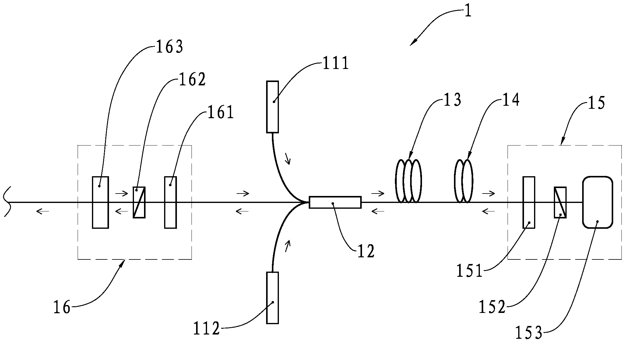
[0031] refer to figure 1 , figure 1 It is a structural diagram of the laser 1 of the present invention. The laser 1 is sequentially provided with a pumping light emitting device 111, a pumping light emitting device 112, a fiber beam combiner 12, a gain fiber 13, a polarization maintaining fiber 14, a resonant cavity 15 and an output cavity 16 in the direction along its optical path, wherein , the resonant cavity 15 is sequentially provided with a collimator 151, a polarization beam splitter 152 and a mode locking device 153 in the direction along the optical path, and the output cavity 16 is provided with a collimator 161, a polarization beam splitter 162 and a output mirror 163 . Preferably, the gain fiber 13 is a double-clad thulium-doped polarization-maintaining fiber, the mode locking device 153 is a semiconductor saturable absorber mirror, and the polarization beam splitting device 152 and polarization beam splitting device 162 are Wollaston prisms or Rochon prisms.

...

no. 2 example

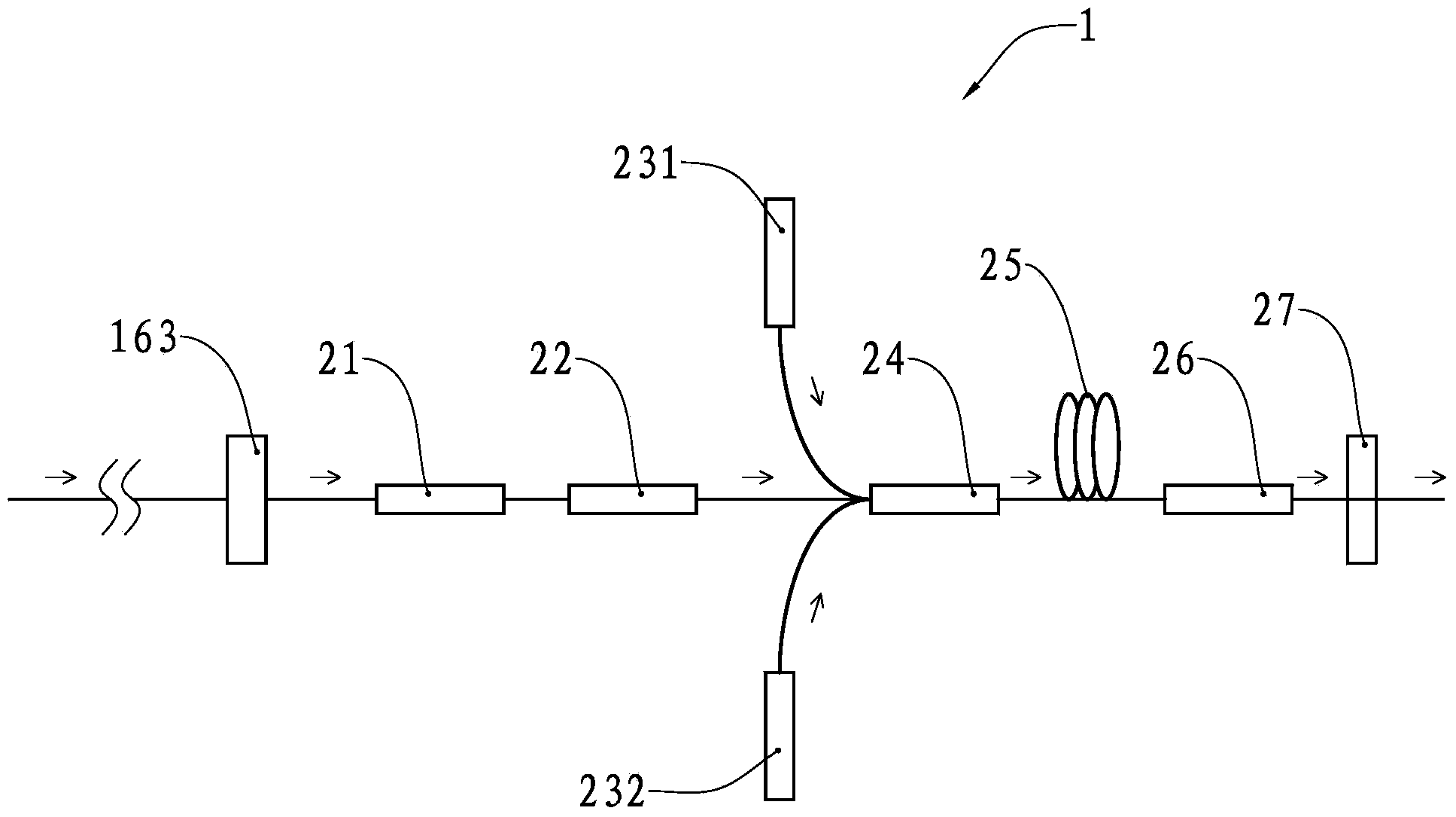
[0038] The laser 1 in this embodiment has a power amplifier, and the power amplifier is located at the output rear stage of the output mirror 163 of the laser 1 in the first embodiment.

[0039] refer to figure 2 , figure 2 It is a structural diagram of the power amplifier of the laser 1. The power amplifier is sequentially provided with an isolator 21, a mode field adapter 22, a pumping light emitting device 231, a pumping light emitting device 232, and a fiber combiner in the direction along its optical path. 24. Gain fiber 25, cladding power stripper 26, collimator 27.

[0040] Collimator 163, isolator 21, mode field adapter 22, pumping light emitting device 231, pumping light emitting device 232, fiber beam combiner 24, gain fiber 25, cladding power stripper 26 and collimator 27 are mutually Both are connected by polarization-maintaining optical fiber.

[0041] After the collimator 163 outputs the mode-locked laser pulse and enters the isolator 21, since the isolator ...


PUM


Abstract

The invention provides a laser, which comprises at least one pump light emitting device, an optical fiber beam combiner, a grain optical fiber, a first aligner, a mold locking device, a second aligner and an output lens, wherein a first polarization beam-splitting device is arranged between the first aligner and the mold locking device on the laser; a second polarization beam-splitting device is arranged between the second aligner and the output lens on the laser; adjacent optical devices are connected by adopting polarization-preserving optical fibers. The laser having a polarization-preserving optical fiber structure is high in stability. Linearly polarized light is transmitted through the polarization-preserving optical fibers, so that the influence of vibration on a light path caused by temperature change is avoided. Moreover, the mold locking device can be used for stably absorbing a part of energy and reflecting laser pulse generated after stable mold locking through the polarization beam-splitting devices.

Description

technical field [0001] The invention relates to a laser, in particular to a fiber laser for outputting mode-locked laser pulses. Background technique [0002] Fiber laser refers to a laser that uses rare earth element-doped glass fiber as the gain medium. Under the action of pump light, it is easy to form a high power density in the fiber, and then cause the laser energy level transition of the laser working material, and then pass through the resonator. Laser oscillation output. [0003] Fiber laser has a wide range of applications. It has the advantages of small size, light weight, high conversion efficiency, and good output beam quality. It has developed rapidly in recent years, especially in laser optical fiber communication, laser space remote communication, industrial shipbuilding, automobile manufacturing, Laser engraving, laser marking, laser cutting, printing rollers, metal and non-metal drilling, cutting, welding, military defense security, medical equipment, larg...

Claims


Application Information

Patent Timeline
Patent Type & Authority Applications(China)
IPC IPC(8): H01S3/067H01S3/08H01S3/02H01S3/13H01S3/098
Inventor 曹丁象卢建南梁文富黎海明
Owner ZHUHAI GUANGKU TECH CO LTD
Why Eureka
Try Eureka