SERS (Surface Enhanced Raman Scattering) probe molecule self-collecting micropipe as well as preparation method and application thereof

A probe molecule and microtubule technology, applied in the field of SERS probe molecule self-collecting microtubule and its preparation, can solve the problems of limiting SERS application and the like

Inactive Publication Date: 2014-05-07
FUDAN UNIV
View PDF4 Cites 12 Cited by
  • Summary
  • Abstract
  • Description
  • Claims
  • Application Information

AI Technical Summary

Problems solved by technology

However, the traditional SERS-enhanced substrates mainly focus on planar precious metal materials, and the detection methods are mostly drop-adding, which severely limits the application of SERS.

Method used


Image

  • SERS (Surface Enhanced Raman Scattering) probe molecule self-collecting micropipe as well as preparation method and application thereof
  • SERS (Surface Enhanced Raman Scattering) probe molecule self-collecting micropipe as well as preparation method and application thereof
  • SERS (Surface Enhanced Raman Scattering) probe molecule self-collecting micropipe as well as preparation method and application thereof

Examples


Embodiment 1

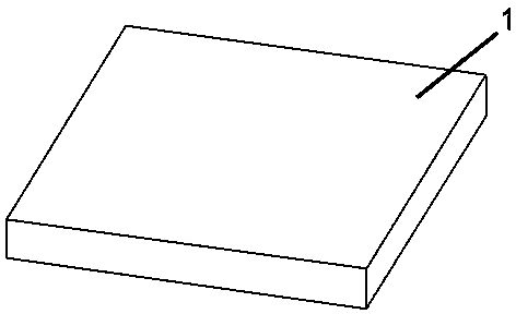
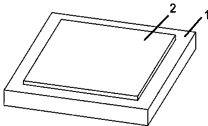
[0033] Si is selected as the substrate; a patterned photoresist layer is set on the Si substrate as a sacrificial layer, and the photoresist layer is covered on the surface of the Si substrate by spin coating, and the spin coating rate is 3000 rpm. The time is 35s.

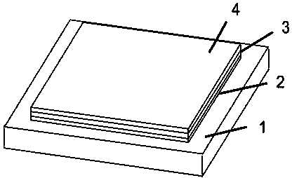
[0034] Using the physical vapor deposition method of electron beam evaporation, a microtube outer wall film with a thickness of 8 nm and made of Au was deposited on the sacrificial layer at a deposition rate of 3 ? / s; The film on the inner wall of the tube, the deposition rate is 0.3 ? / s;

[0035] Among them, during the deposition process, by changing the deposition parameters, such as deposition rate, substrate temperature and deposition pressure, etc., a thin film with required parameters can be prepared.

[0036] Make an angle of 60 degrees between the normal direction of the substrate and the incident direction of the evaporation source (7), such as Figure 7 As shown, there is a shadow effect in the deposit...

Embodiment 2

[0040] Similar to the previous embodiment, electron beam evaporation is used to deposit a thin film on the above-mentioned Si substrate covered with a sacrificial layer, and the material used is Au / TiO 2 / Pt, the deposition thickness is 8 nm / 8 nm / 6 nm, and the deposition rate is 3 ? / s, 0.5 ? / s, and 0.3 ? / s, respectively.

[0041]The crimping process is done by a supercritical dryer. The sample is immersed in acetone, and the sacrificial layer is removed with acetone to release the stress, so that the film above the sacrificial layer is curled up to form microtubes.

[0042] Put the obtained microtubules into a solution of ethanol with a lipoic acid content of 2.5mmol / L, soak for 14 hours to form a self-assembled monolayer on the outer surface, then rinse with deionized water, and finally obtain a self-assembled monolayer on the outer surface The membrane, ie the SERS probe molecules self-collecting microtubules.

[0043] Put the above sample into the triphenylmethane content...


PUM

PropertyMeasurementUnit
thicknessaaaaaaaaaa

Abstract

The invention belongs to the technical field of micro-nano devices, and particularly relates to an SERS (Surface Enhanced Raman Scattering) probe molecule self-collecting micropipe as well as a preparation method and an application thereof. The preparation method comprises the steps: preparing a substrate, making a sacrificial layer on the substrate; depositing film layers of different materials with internal stress on the sacrificial layer, wherein the materials of the deposited film layers are capable of providing better SERS characteristics or capable of catalytically decomposing H2O2 to generate oxygen; selectively removing the sacrificial layer between the film layer and the substrate, releasing a film and coiling into a micropipe; and immersing the micropipe in a solution containing a defined amount of coupling agent for certain time, forming a self-assembled single-layer film on the outer surface of the micropipe, and finally obtaining the SERS probe molecule self-collecting micropipe. The device can be used for collecting and detecting a probe molecule in the solution. An SERS signal of the probe molecule is measured by a Raman spectrometer.

Description

technical field [0001] The invention belongs to the technical field of micro-nano devices, and in particular relates to a self-collecting microtube for SERS probe molecules and its preparation method and application. Background technique [0002] Surface-enhanced Raman Scattering (SERS) can directly provide important information such as surface molecular structure and dynamic process from the molecular level, so it is widely used in surface adsorption, chemical biosensors, biomedical detection and analysis, etc. . However, the traditional SERS-enhanced substrates mainly focus on planar precious metal materials, and the detection methods are mostly drop-adding, which severely limits the application of SERS. At the same time, the signal sensitivity of SERS is directly proportional to the number of probe molecules adsorbed on the substrate. Increasing the number of probe molecules is an effective way to improve the sensitivity of SERS substrates. Dynamic collection of probe mo...

Claims


Application Information

Patent Timeline
Patent Type & Authority Applications(China)
IPC IPC(8): C23C14/04G01N21/65B82Y30/00B82Y40/00
Inventor 韩迪黄高山刘照乾张艳邱腾梅永丰
Owner FUDAN UNIV
Why Eureka
Try Eureka