Catalytic cracking method

A technology of catalytic cracking and standby catalyst, which is applied in catalytic cracking, cracking, petroleum industry, etc. It can solve the problems of high contact temperature between regenerated catalyst and raw oil, catalytic gasoline cannot be modified separately, and catalyst back-mixing, etc., to achieve shortening Effect of residence time, improvement of charring intensity and charring efficiency, and reduction of secondary reactions

Inactive Publication Date: 2014-05-14
CHINA PETROCHEMICAL CORP +1
View PDF7 Cites 5 Cited by
  • Summary
  • Abstract
  • Description
  • Claims
  • Application Information

AI Technical Summary

Problems solved by technology

[0008] The invention provides a catalytic cracking method suitable for processing residual carbon less than 0.5% by weight, so as to overcome the high contact temperature between the regenerated catalyst and raw oil, low ratio of agent to oil, long reaction time, and reaction problems existing in the existing catalytic cracking process. Disadvantages such as severe back-mixing of the catalyst in the tank, low regeneration efficiency, and the inability to upgrade catalytic gasoline independently

Method used


Image

  • Catalytic cracking method
  • Catalytic cracking method
  • Catalytic cracking method

Examples


Embodiment 1

[0065] Example 1, Comparative Example

[0066] The test was carried out on a conventional double riser catalytic cracking pilot plant. The heavy oil riser reactor processes the Luning pipe to transport straight-run wax oil, and the light hydrocarbon riser reactor processes the catalytic gasoline produced by the heavy oil riser reactor. The catalyst is a commercial CC-20D catalytic cracking industrial equilibrium catalyst.

[0067] The designed processing capacity of the heavy oil riser reactor is 60kg / d, which simulates the full refining operation. The heavy oil raw material and the refining oil are mixed and enter the heavy oil riser reactor through the feed nozzle; the light hydrocarbon riser reactor is designed to handle 24kg / d . The carbon content of the regenerated catalyst is 0.03w%, and the slight reaction activity is 62. The stripping medium in the stripping section is steam, and the stripping temperature is 500°C.

[0068] The properties of the catalytic cracking raw mate...

Embodiment 2

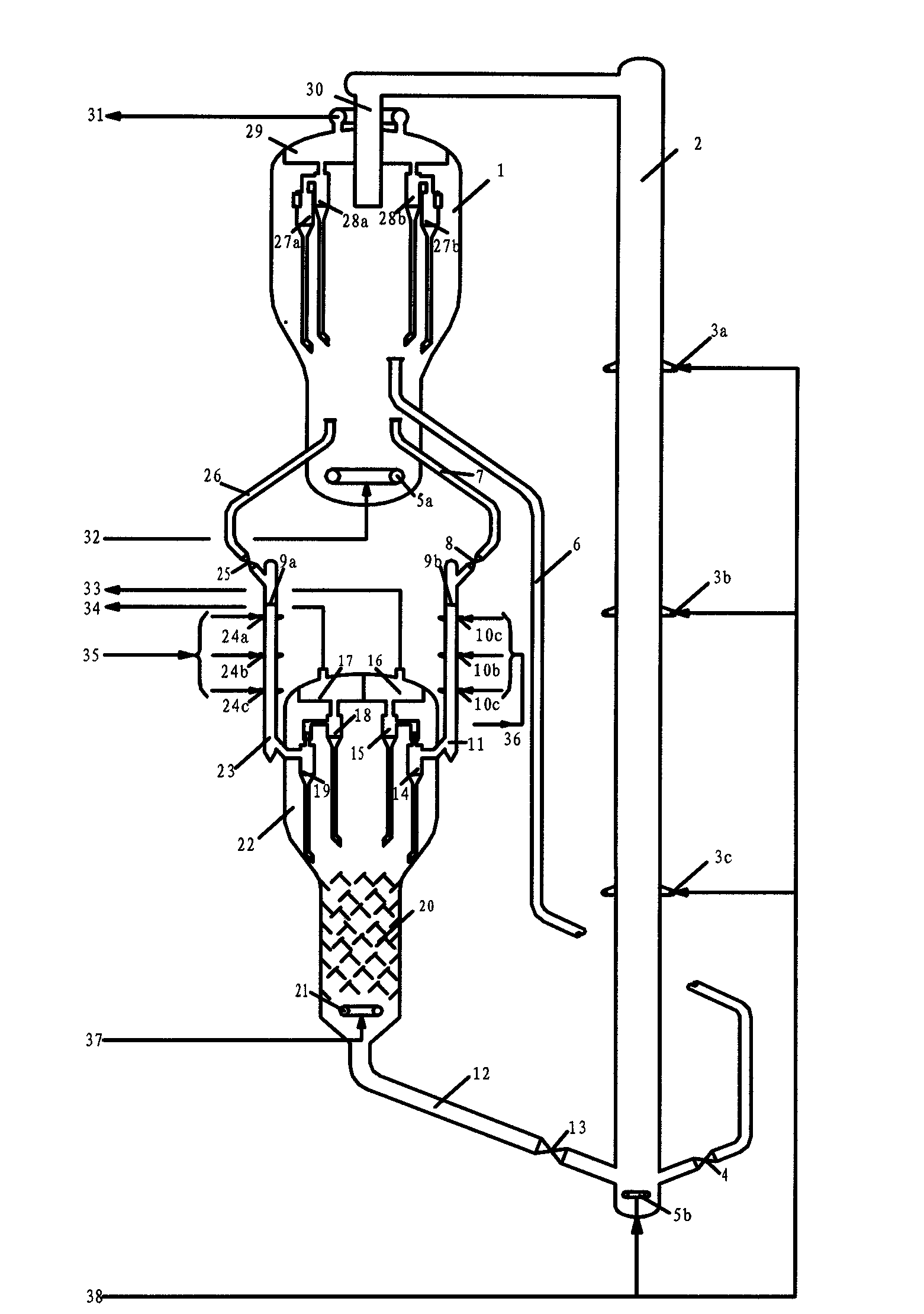
[0070] in figure 1 The test was carried out on the new fluidized catalytic cracking pilot plant shown. Both the heavy oil downcomer reactor and the light hydrocarbon downcomer reactor of the new fluid catalytic cracking pilot plant can be flexibly replaced according to process requirements. The heavy oil down tube reactor processes the same Luning tube conveying straight-run wax oil as the comparative example, and the light hydrocarbon down tube reactor processes the heavy oil down tube reactor to produce catalytic gasoline. The catalyst uses the same commercial CC-20D catalyst as the comparative example. Balanced catalyst for cracking industry.

[0071] The designed processing capacity of the heavy oil downcomer reactor is 60kg / d, simulating a full refining operation, the heavy oil feedstock is mixed with the refining oil and then enters the heavy oil downcomer reactor through the feed nozzle; the light hydrocarbon downcomer reactor is designed to handle 30kg / d , The carbon con...

Embodiment 3

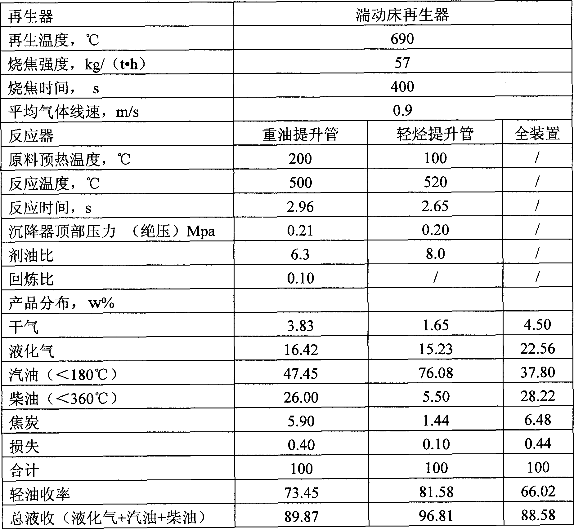
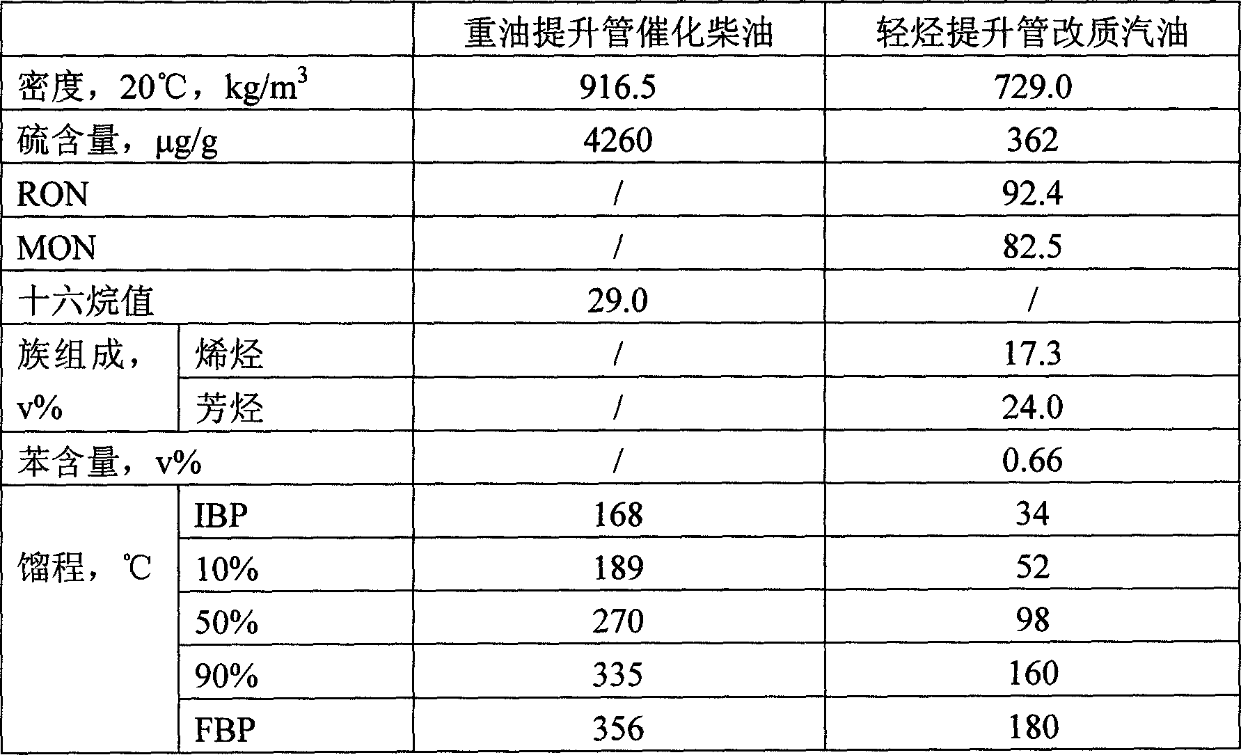
[0074] According to Example 2, the main differences are the scorching intensity and scorch time of the turbulent bed regenerator and the riser regenerator, the average gas linear velocity of the riser regenerator, the reaction time and the refining ratio of the heavy oil downcomer reactor. The main operating conditions and product distribution of the new fluidized catalytic cracking unit in this implementation are shown in Table 6. The main properties of the liquid products of the new fluid catalytic cracking unit are shown in Table 7.


PUM


Abstract

The invention discloses a catalytic cracking method. The method comprises the following steps: two descendent tube reactors capable of multipoint feeding are adopted to respectively perform heavy oil catalytic cracking and light hydrocarbon catalytic reforming; two reactant streams flow into a precipitator and are respectively subjected to gas-solid separation by different cyclone separators; a mixed regenerative agent is subjected to steam stripping, enters a multipoint-air-intake riser regenerator to be mixed with a regenerated catalyst stream to perform charring regeneration; the generated semi-regenerated catalyst enters a turbulent bed regenerator to be subjected to charring regeneration; the regenerated catalyst returns to the two reactors for cyclic use; and heavy oil reaction oil gas and light hydrocarbon reaction oil gas are respectively fractionated by the respective special fractionating towers. The method can improve the catalytic cracking product distribution, enhance the light oil yield and lower the yield of the cracked gas and coke; the method can be used for producing low-olefin-content catalytic gasoline and high-cetane-number catalytic diesel; and the method enhances the charring efficiency and decelerates the hydrothermal inactivation of the catalyst.

Description

Technical field [0001] The invention belongs to the field of catalytic cracking of hydrocarbon oil in the absence of hydrogen, and particularly relates to a catalytic cracking method. Background technique [0002] At present, although the equipment used in the catalytic cracking process of the petrochemical industry is diverse, the process form of the reaction regeneration system is basically the same. Most of them use a single riser reactor (or a combination of a single riser and a fast bed). Sectional reactor) and turbulent bed regenerator (or a two-stage regenerator combining turbulent bed and fast bed). The catalyst and the feed oil are contacted and mixed at the bottom of the riser and then reacted upward along the riser. The reactant stream enters the settler from the top outlet of the riser to separate the reaction oil and gas and the catalyst; the separated spent catalyst is subjected to a regular stripping in the stripping section. Enter the regenerator to burn and rege...

Claims


Application Information

Patent Timeline
Patent Type & Authority Applications(China)
IPC IPC(8): C10G11/00
Inventor 陈曼桥王文柯武立宪张亚西孟凡东樊麦跃陈章淼黄延召李秋芝吴辰捷
Owner CHINA PETROCHEMICAL CORP
Why Eureka
Try Eureka