FPGA (field programmable gate array) based implementation method of phased array antenna iteration phase-matching algorithm

A technology of phased array antenna and implementation method, which is applied in computing, special data processing applications, instruments, etc., and can solve the problems of slow running speed of algorithms, large consumption of FPGA hardware resources, and inability to improve system performance, etc.

Active Publication Date: 2014-05-21
CNGC INST NO 206 OF CHINA ARMS IND GRP
View PDF6 Cites 14 Cited by
  • Summary
  • Abstract
  • Description
  • Claims
  • Application Information

AI Technical Summary

Problems solved by technology

If the floating-point method is used to implement the iterative matching algorithm, the consumption of FPGA hardware resources will be large and the running speed of the algorithm will be slow, which cannot improve the system performance.

Method used


Image

  • FPGA (field programmable gate array) based implementation method of phased array antenna iteration phase-matching algorithm
  • FPGA (field programmable gate array) based implementation method of phased array antenna iteration phase-matching algorithm
  • FPGA (field programmable gate array) based implementation method of phased array antenna iteration phase-matching algorithm

Examples


specific Embodiment approach

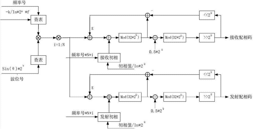
[0087] For a specific antenna structure, it is necessary to first establish a frequency signal lookup table, a wave position signal lookup table, a receiving initial phase lookup table, and a transmitting initial phase lookup table; the specific steps are:

[0088] 1. Establish a frequency signal lookup table: Call the parameterized module library ROM:1-PORT in the FPGA development software QuartusII of Altera Corporation, and establish a frequency signal search ROM ROM_Freq; ROM_Freq calls its corresponding MIF file during the instantiation process to complete the ROM storage Unit and frequency signal data mapping;

[0089] The content of the MIF file: the form data of the MIF file is set as signed integer data, the total amount of data is the total number of frequency points n of antenna work, and the data content is round(-k / In×2 a ×f). Among them, round() is a rounding function; k is the antenna element distribution constant, and the data format is a floating point consta...

Embodiment 1

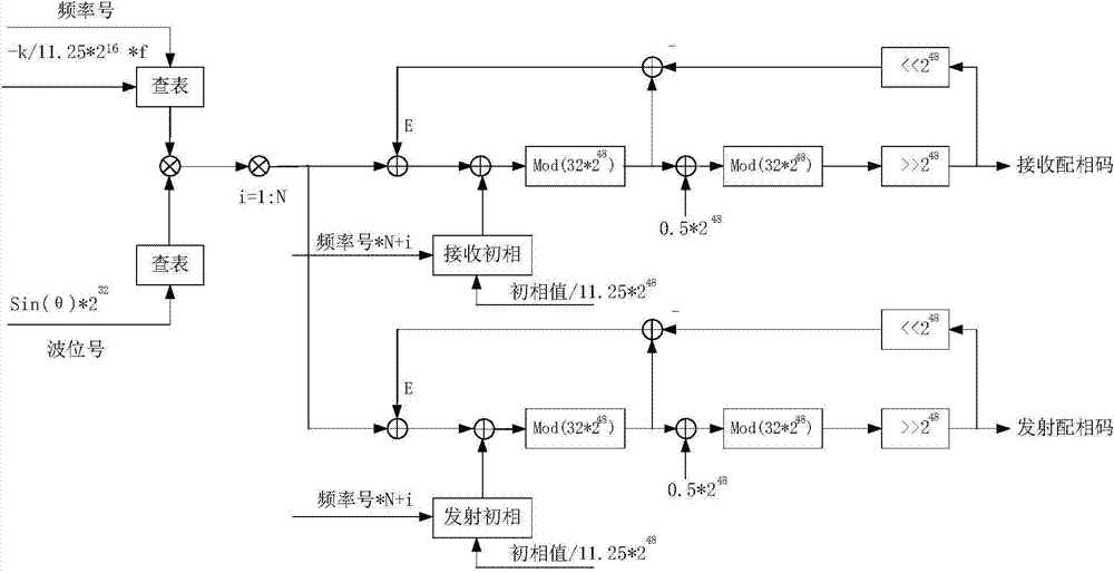
[0130] The minimum step of the phase shifter required by the antenna system is 11.25°, that is, a 5-bit digital phase shifter is used to realize the phase shifting system. The number of phase shifting units is 96, and the iterative phase matching operation and code value transmission of all phase shifting units need to be completed within 100us.

[0131] Taking into account the system operation speed and operation accuracy, the clock frequency of the counter is designed to be 10MHz, and the expansion multiple is 2 Q The exponential factor Q in is 48. figure 2 Block diagram for the FPGA implementation of the algorithm.

[0132] figure 2 Among them, the number of phase-shifting units is N=96; the distribution constant of antenna elements k=5.5; f is the current operating frequency of the antenna; θ is the required pointing angle of the antenna beam. According to this algorithm, the iterative phase matching calculation of 96 phase-shifting units takes 96×1 / 10MHz=9.6us, and t...

Embodiment 2

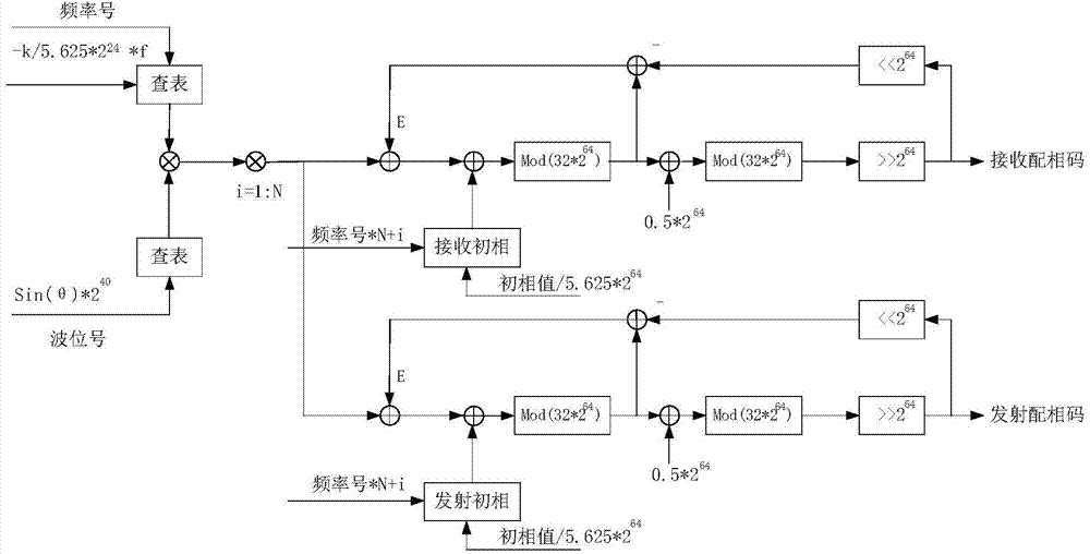
[0134] The minimum step of the phase shifter required by the antenna system is 5.625°, that is, a 6-bit digital phase shifter is used to realize the phase shifting system. The number of phase shifting units is 51, and the iterative phase matching operation and code value transmission of all phase shifting units need to be completed within 50us.

[0135] Taking into account the system operation speed and operation accuracy, the counter clock frequency is 5MHz, and the expansion multiple is 2 Q The exponential factor Q in is 64. image 3 Block diagram for the FPGA implementation of the algorithm.

[0136] image 3 Among them, the number of phase-shifting units N=51; the distribution constant of antenna array elements k=11.7; f is the current operating frequency of the antenna; θ is the required pointing angle of the antenna beam. According to this algorithm, the iterative phase matching calculation of 51 phase-shifting units takes 51×1 / 5MHz=10.2us, and the operation speed gre...


PUM


Abstract

The invention provides an FPGA (field programmable gate array) based implementation method of a phased array antenna iteration phase-matching algorithm. The parallel running characteristic of FPGA hardware is used, the iteration phase-matching algorithm is realized through algorithm optimization, and the operating speed and the operating precision of the iteration phase-matching algorithm are improved. According to the method, the operating speed is decided by the clock frequency of a counter, and the clock frequency of the counter can reach 200 MHz (related to an adopted FPGA hardware platform) through optimization of the FPGA design, that is, the phase-matching iteration computing time for completing receiving and sending of a phase-matching code of one phase shift unit is 5 ns. The operating precision is decided by an enlargement multiple 2Q, the larger the enlargement multiple is, the smaller the rounding error noise is, the higher the operating result precision is, and the higher the antenna beam-pointing accuracy is. However, the increase of the enlargement multiple can affect the optimization effect of the clock frequency of the counter and decrease the operating speed, so that both the operating speed and the operating precision are required to be considered in the actual design process.

Description

technical field [0001] The invention belongs to the field of phased array antennas, and relates to a method for realizing an iterative matching algorithm of an FPGA-based phased array antenna, which is applied to improving the operation speed and accuracy of the iterative matching algorithm. Background technique [0002] The iterative matching algorithm is a matching code calculation method used in the field of phased array antennas. In this algorithm, the quantization error generated after the quantization of the theoretical phase shift value calculated by the current phase shifting unit is brought into the phase matching code calculation of the next phase shifting unit, which is beneficial to reduce the quantization noise of the phase shifting system and can effectively improve Antenna beam pointing accuracy. The difference between this algorithm and the common phase matching algorithm is that there is an iterative relationship between the calculation of the phase matchin...

Claims


Application Information

Patent Timeline
Patent Type & Authority Applications(China)
IPC IPC(8): G06F17/50
Inventor 江承财邓龙波张军李晓航张小虎李涛云龙陈君王凌
Owner CNGC INST NO 206 OF CHINA ARMS IND GRP
Why Eureka
Try Eureka