
Magnetic pulse forming equipment and method for connecting dissimilar metal rod and metal plate structural member

A magnetic pulse forming, dissimilar metal technology, applied in metal processing equipment, welding equipment, metal processing and other directions, can solve the problems of easy cracking of welded joints, unfavorable connection of dissimilar metals, and no use of Joule heating effect, etc., to achieve high efficiency and eliminate damage. Effect

Active Publication Date: 2014-06-04
HARBIN INST OF TECH
View PDF8 Cites 7 Cited by
  • Summary
  • Abstract
  • Description
  • Claims
  • Application Information

AI Technical Summary

Problems solved by technology

However, in the general magnetic pulse forming process, the pulse high current only flows through the coil, which is completely insulated from the workpiece, and there is only induced current in the workpiece, and the external pressure used in capacitor discharge welding is only used for limiting. Therefore, the magnetic pulse forming process has no Utilize the Joule heating effect generated by the large current flowing through the contact interface, while the capacitor discharge welding uses arc heat to melt the metal at the rod-plate interface, and the connection is realized through the process of melting and solidification, but this process is unfavorable for the connection of dissimilar metals, often Creates brittle intermetallic compounds and stress concentrations in welded joints, resulting in welded joints that are prone to cracking

Method used


Image

  • Magnetic pulse forming equipment and method for connecting dissimilar metal rod and metal plate structural member
  • Magnetic pulse forming equipment and method for connecting dissimilar metal rod and metal plate structural member
  • Magnetic pulse forming equipment and method for connecting dissimilar metal rod and metal plate structural member

Examples


specific Embodiment approach 1

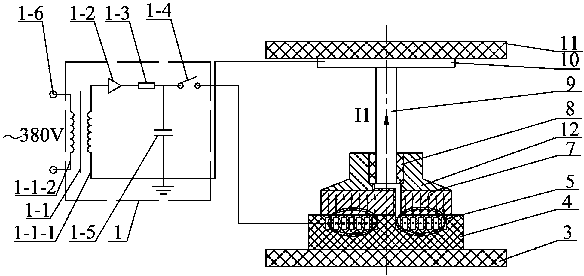
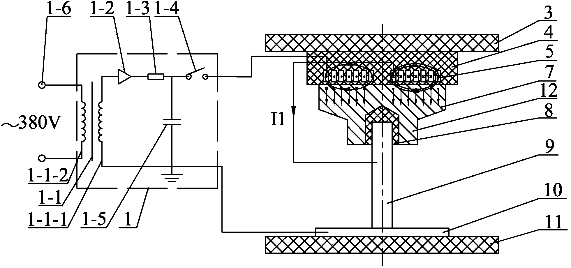
[0024] Specific implementation mode one: as figure 1As shown, the magnetic pulse forming equipment in which dissimilar metal rods and metal plate structural parts are connected in this embodiment, the magnetic pulse forming equipment includes a magnetic pulse control circuit 1 (for generating a large pulse current), a pressure plate 3, and an insulating coil bobbin 4. Coil 5, drive block 7, insulating sleeve 8, metal guide sleeve 12 and pressure plate 2 11;

[0025] The coil 5 is placed on the upper end surface of the pressure plate 3, the coil 5 is an insulating coil (the outer surface of the coil 5 is covered with insulating material, which is a high-voltage insulating material), the coil 5 is potted in the insulating coil skeleton 4, and the insulating coil The skeleton 4 is fixedly connected to the upper end surface of the pressure plate 1, the driving block 7 is set on the upper end surface of the insulating coil skeleton 4, the metal guide sleeve 12 is fixed on the upper...

specific Embodiment approach 2

[0026] Specific implementation mode two: combination figure 1 Explain that the magnetic pulse control circuit 1 in this embodiment includes a high voltage transformer 1-1, a rectifier 1-2, a current limiting resistor 1-3, a high voltage switch 1-4, a high voltage pulse capacitor 1-5 and an AC power supply 1-6 ;

[0027] One end of the secondary coil 1-1-1 of the high voltage transformer 1-1 is connected to the anode of the rectifier 1-2, the cathode of the rectifier 1-2 is connected to one end of the current limiting resistor 1-3, and the current limiting resistor 1 The other end of -3 is connected with the positive pole of the high-voltage pulse capacitor 1-5 and the positive pole of the high-voltage switch 1-4, and the negative pole of the high-voltage switch 1-4 is used as the said one output end of the magnetic pulse control circuit 1, and the high-voltage transformer 1-1 The other end of the secondary coil 1-1-1 is connected to the negative pole of the power supply groun...

specific Embodiment approach 3

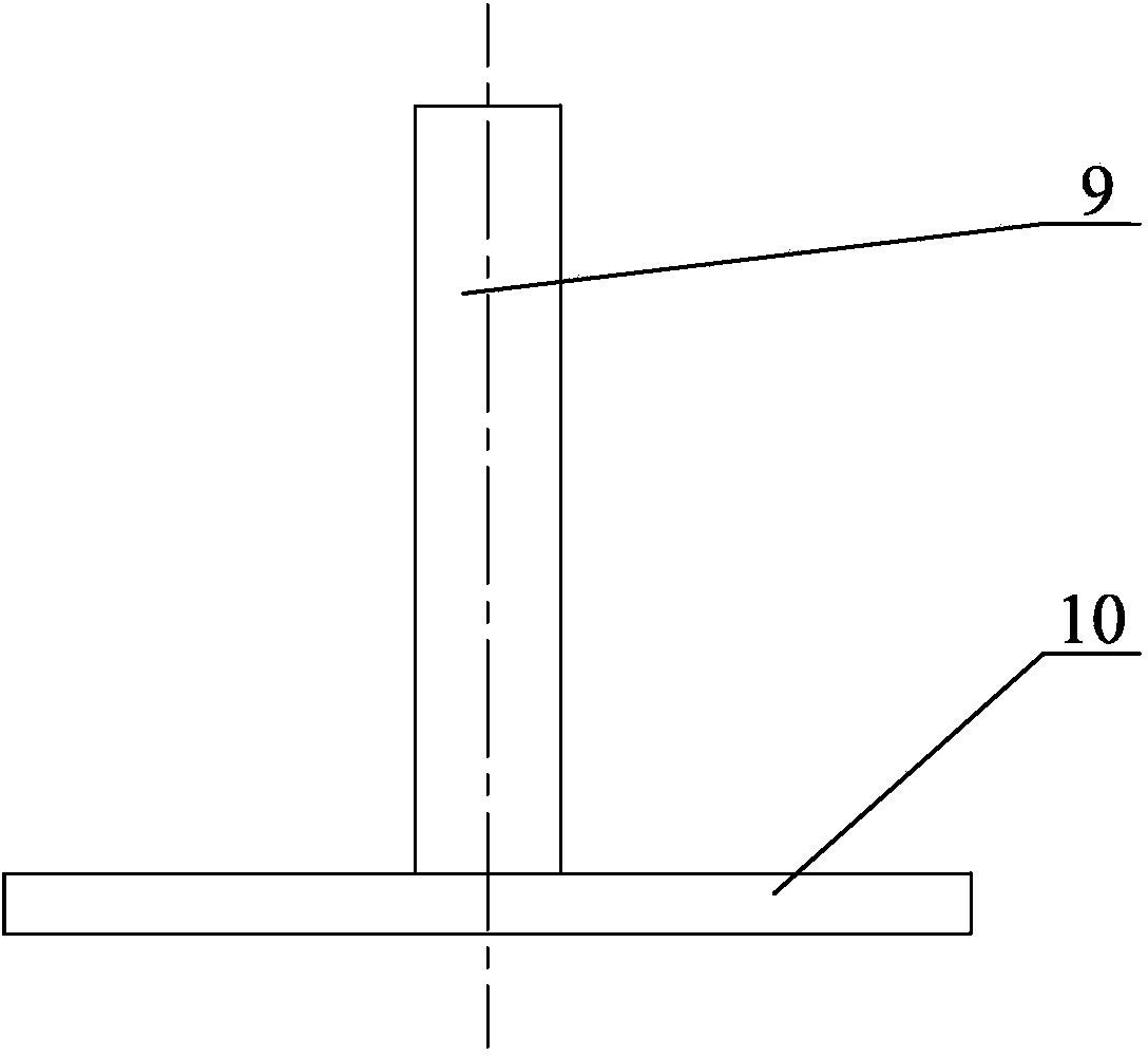
[0028] Specific implementation mode three: combination figure 1 and image 3 To illustrate, the method of using magnetic pulse forming equipment in this embodiment to realize the connection of dissimilar metal rods and metal plate structural parts, the method steps are:

[0029] Step 1: Charge the high-voltage pulse capacitor 1-5; inside the magnetic pulse forming equipment, after the voltage of the external network is boosted by the high-voltage transformer 1-1, the voltage rises to 1000-5000 volts, and the power-frequency alternating current is converted by the rectifier 1-2 It becomes DC, and then DC charges the high-voltage pulse capacitor 1-5 through the current-limiting resistor 1-3. The capacitance of the high-voltage pulse capacitor 1-5 is 800-4000 microfarads. When it is charged to a predetermined voltage value, it is disconnected by the high-voltage transformer 1-1, a charging circuit composed of a rectifier 1-2, a current-limiting resistor 1-3 and a high-voltage pu...


PUM

PropertyMeasurementUnit
capacitanceaaaaaaaaaa
tensile strengthaaaaaaaaaa
compressive strengthaaaaaaaaaa

Abstract

The invention provides a magnetic pulse forming equipment and method for connecting a dissimilar metal rod and metal plate structural member, and belongs to the field of connection of dissimilar metals. The flat coil current and the instantaneous impact load are simultaneously applied to metal rod and metal plate structural member welding, so that defect that the external pressure for capacitor discharge welding is only applied to limitation can be overcome, the liquid phase connecting mechanism under the action of capacitor discharge welding arcs can be changed, and the solid-state connection of the dissimilar metal rod and metal plate structural member can be realized under actions of the flat coil current and instantaneous impact load. An insulating coil bobbin and a pressing plate are fixedly connected, a drive block is arranged on the insulating coil bobbin, a metal guide sleeve is fixed to the drive block, two output ends of a magnetic pulse control circuit are connected to the coil and the metal plate structural member, the coil is fixedly connected to the drive block, an insulating sleeve is embedded in the metal guide sleeve, the metal rod is embedded in the insulating sleeve, the metal plate structural member tightly contacts with the pressing plate, and the coil is tightly connected to the metal rod electrically. The equipment and method is applied to the dissimilar metal rod and metal plate structural member connection.

Description

technical field [0001] The invention relates to a forming device and method for connecting dissimilar metal rods and metal plate structural parts, and belongs to the field of dissimilar metal material connection. Background technique [0002] Metal rods and metal plate structural parts are widely used in engineering and technical fields such as ships, special vehicles, and construction. Generally, the metal rods are screw-type fasteners, sleeves and nails with a diameter of 5-25 mm, and the materials are ferromagnetic or non-ferromagnetic metals and their alloys. The sheet metal structure is often a shell structure obtained by forming a sheet metal, with a thickness of 1 to 10 mm. [0003] Attaching metal rod fasteners to metal housing structures is difficult, often requiring steps such as welding intermediate transitions, drilling holes, and threading the metal rods. This process is generally completed by manual arc welding, gas shielded welding or resistance projection w...

Claims


Application Information

Patent Timeline
Patent Type & Authority Applications(China)
IPC IPC(8): B23P11/00
CPCB23K20/06B23K2103/18
Inventor 于海平李春峰孙立超
Owner HARBIN INST OF TECH
Learn More