Eureka AIR delivers breakthrough ideas for toughest innovation challenges, trusted by R&D personnel around the world.

A kind of carbon nanotube growth method and its emitter for the growth of boat groove pattern structure

A carbon nanotube and growth method technology, applied in the field of electron sources, can solve the problems of difficult emission current, small total emission current, limited application, etc., and achieve the effect of improving field emission current

Inactive Publication Date: 2015-08-12
南京康众光电科技有限公司
View PDF4 Cites 0 Cited by
  • Summary
  • Abstract
  • Description
  • Claims
  • Application Information

AI Technical Summary

Problems solved by technology

In theory, carbon nanotubes with uniform array distribution and high orientation should obtain a larger emission current. However, so far, they have not been widely used in practical applications, indicating that there are still many shortcomings in perfect array growth. In order to obtain large The field emission performance of current needs further discussion and technical improvement; through existing research, it is found that the electron emission ability of carbon nanotubes is closely related to factors such as array structure, type, and shape. Further explore its structure and growth techniques, etc.
[0004] Recently, the research on the field emission performance of aligned carbon nanotube arrays has the following problems: (1) Although the literature has reported a large emission current density, which is only obtained on a small emission area, the total emission current is still small. There are some difficulties in obtaining a large emission current from an area emission source. Some literatures have reported that a large emission current can be obtained by electrophoretic deposition, so the emission performance of the carbon nanotube arrays currently prepared cannot meet the requirements of devices that require current. ; (2) There are serious problems in emission stability and uniformity, which limit its application in field emission devices; for example, although electrophoretic deposition can obtain better emission current, there are some problems in its deposition uniformity; Although the method can obtain considerable emission current, it is difficult to control the printing area, deposition thickness and uniformity; in short, in order to obtain a more perfect emitter sample and present excellent field emission performance, further exploration and research are still needed

Method used


Image

  • A kind of carbon nanotube growth method and its emitter for the growth of boat groove pattern structure
  • A kind of carbon nanotube growth method and its emitter for the growth of boat groove pattern structure
  • A kind of carbon nanotube growth method and its emitter for the growth of boat groove pattern structure

Examples


Embodiment

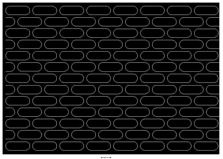
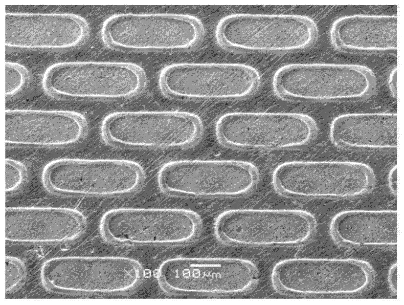
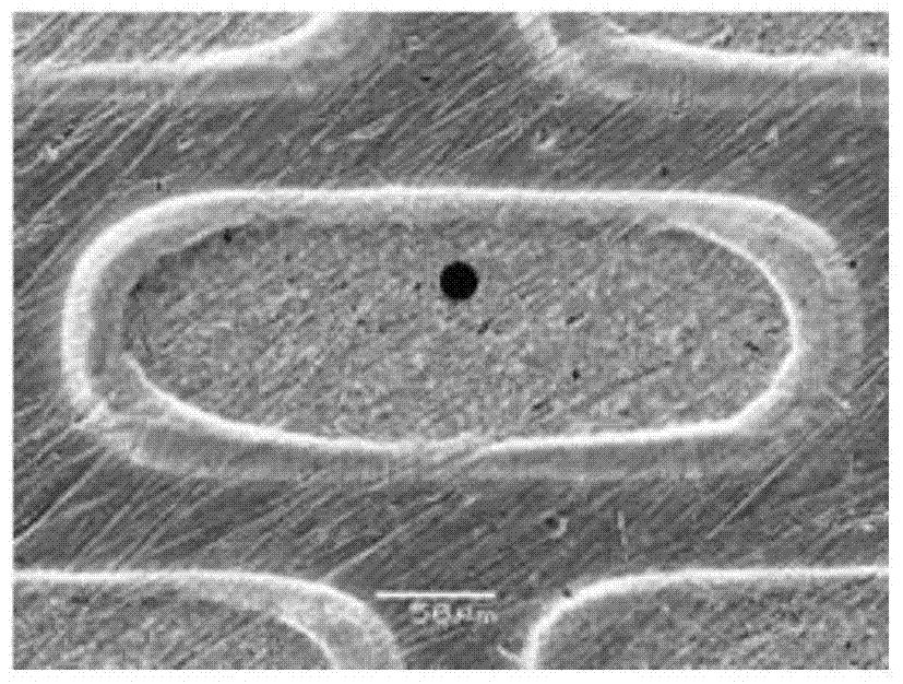
[0032] In an embodiment, the preparation process of carbon nanotubes grown with a new patterned structure in a boat trough is as follows:

[0033] (1) First select the substrate material. Here, molybdenum sheet is selected as the substrate. Silicon sheet, stainless steel, ITO conductive glass or quartz sheet can also be used. There is no significant difference in the obtained samples. The base sheet was ultrasonically cleaned with dilute acid, acetone, ethanol and secondary water for 30 minutes to remove organic matter and other impurities on the surface, and to remove surface moisture under a nitrogen atmosphere; the dilute acid was 1mol / L dilute hydrochloric acid, 1mol / L / L dilute nitric acid, 0.5mol / L dilute sulfuric acid or some 0.1mol / L weak acid (such as acetic acid, etc.).

[0034] (2) Select a 0.1mm thick stainless steel material to prepare a pattern template with a boat groove pattern structure by laser cutting technology or electron beam technology, and the pattern c...


PUM

PropertyMeasurementUnit
heightaaaaaaaaaa
widthaaaaaaaaaa
thicknessaaaaaaaaaa

Abstract

The invention provides a growing method for carbon nanotubes growing according to a headchute type pattern structure. The method comprises the following steps: controlling of catalyst deposition and growth conditions and selection of a novel mask plate pattern structure and thickness thereof; and growth of a carbon nanotube emitter through hot chemical vapor deposition and plasma enhanced chemical vapor deposition. Thus, carbon nanotubes growing in the manners of array vertical growth and unordered vertical and horizontal growth are obtained; the carbon nanotubes growing in the manner of array vertical growth have height of 15 to 20 mu m and width of 4 to 6 mu m; unordered growth occurs in the pattern, the carbon nanotubes growing in the manner of unordered vertical and horizontal growth are surrounded by the carbon nanotubes growing in the manner of array vertical growth, and the thickness of the carbon nanotubes is equal to the diameter of a plurality of layers or tens of layers of nanotubes. Such a composite growth structure has uniformity of an array structure and considerable unordered carbon nanotube tips, which enables field emission current of the emitter of the carbon nanotubes to be effectively improved.

Description

technical field [0001] The invention relates to a method for growing carbon nanotubes which significantly improves field emission performance. The invention is suitable for field emission devices with higher requirements on emission current, for example, the internal electron sources of X-ray sources, microwave amplifiers and field emission scanning electron microscopes. Background technique [0002] Carbon nanotubes are one of the main materials for field emission research at present, and have very bright prospects. Many research institutions at home and abroad are actively working hard to realize the practical application and industrialization of carbon nanotubes in the field of field emission. In the existing carbon nanotubes and related research fields, in order to improve the field emission performance, new structures, materials and process methods are constantly being explored. However, for the current numerous emission materials and their device structures, their str...

Claims


Application Information

Patent Timeline
Patent Type & Authority Patents(China)
IPC IPC(8): C01B31/02H01J29/04B82Y40/00B82Y30/00C01B32/162
Inventor 屈虎刘春毅张研
Owner 南京康众光电科技有限公司
Why Eureka
Eureka Blog
Learn More