Graphene field emission cathode and preparation method thereof
A technology for emitting cathodes and graphene, which is applied in the field of field emission, can solve problems such as increasing the field emission current of graphene field emission cathodes, and achieve the effects of improving emission stability, reducing work function, and reducing the opening electric field
- Summary
- Abstract
- Description
- Claims
- Application Information
AI Technical Summary
Problems solved by technology
Method used
Image
Examples
preparation example Construction
[0041] The embodiment of the present invention also provides the preparation method of graphene field emission cathode as described above, and described preparation method comprises the following steps:
[0042] S10, providing the conductive substrate and performing cleaning treatment.
[0043] In a specific technical solution, the cleaning treatment may specifically include: placing the conductive substrate in deionized water and absolute ethanol in sequence for ultrasonic cleaning, and then drying it with nitrogen gas for later use.
[0044] S20, preparing a mixed solution containing graphene oxide and target metal ions.
[0045] In a preferred solution, the step S20 includes:
[0046] S21. Prepare a graphene oxide nanosheet dispersion.
[0047] Specifically, the prepared graphene oxide nanosheets are added into deionized water, and dispersed by ultrasonic dispersion, the ultrasonic power is 100W-200W, and the time is 1h-3h. After the ultrasonication is over, centrifugation...
Embodiment 1
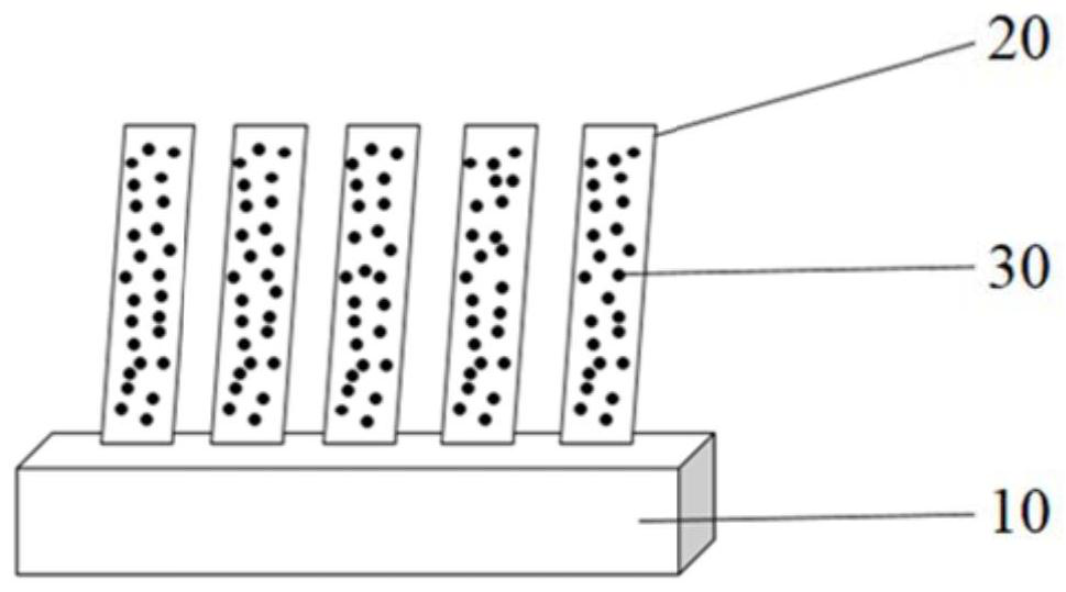
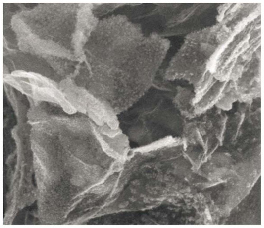
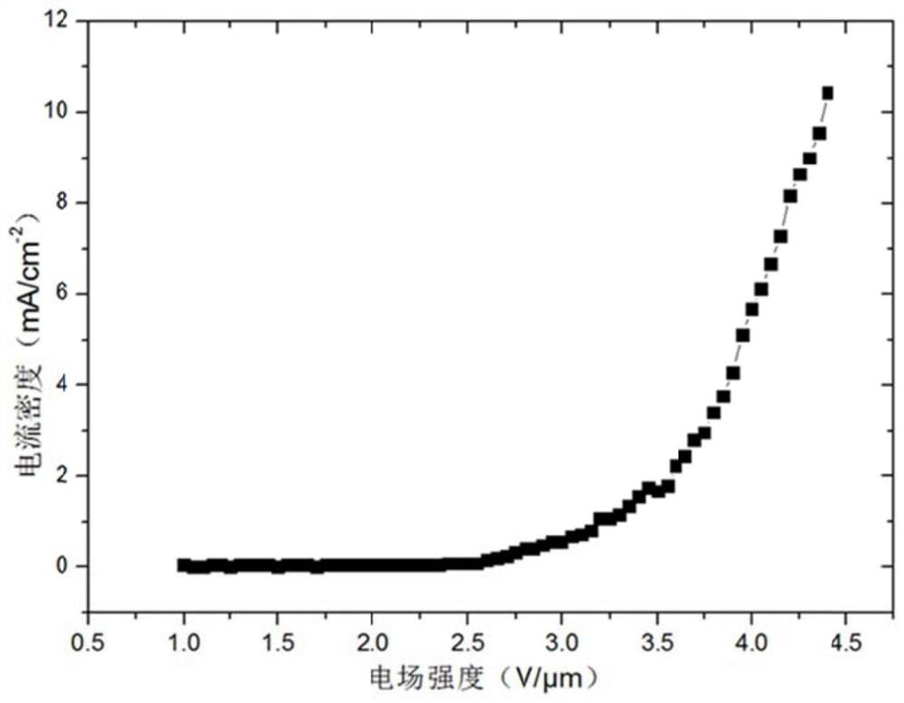
[0060] The present embodiment provides a graphene field emission cathode, the conductive base of the graphene field emission cathode is selected as a titanium substrate, on the titanium substrate growth is upright graphene nanosheets, combined with the graphene nanosheets on the surface of the graphene nanosheets The metal nanoparticles are palladium nanoparticles. The preparation process of the graphene field emission cathode of the present embodiment is as follows:
[0061] 1) The titanium conductive substrate was ultrasonically cleaned in deionized water and absolute ethanol for 10 min, and then dried with nitrogen.
[0062] 2) ultrasonically disperse multilayer graphene oxide with a lateral size of 1 μm to 10 μm and a thickness of 1 nm to 3 nm in deionized water to form a graphene oxide dispersion with a concentration of 0.1 g / L, and add Na 2 PdCl 4 Dissolved in deionized water to give Na 2 PdCl 4 aqueous solution. Then, Na 2 PdCl 4 The aqueous solution was added to...
Embodiment 2
[0068] The present embodiment provides a graphene field emission cathode, the conductive base of the graphene field emission cathode is selected as a titanium substrate, on the titanium substrate growth is upright graphene nanosheets, combined with the graphene nanosheets on the surface of the graphene nanosheets The metal nanoparticles are platinum nanoparticles. The preparation process of the graphene field emission cathode of the present embodiment is as follows:
[0069] 1) The titanium conductive substrate was ultrasonically cleaned in deionized water and absolute ethanol for 10 min, and then dried with nitrogen.
[0070] 2) Ultrasonic disperse multilayer graphene oxide with a lateral size of 1 μm to 10 μm and a thickness of 1 nm to 3 nm in deionized water to form a graphene oxide dispersion with a concentration of 0.2 g / L, and mix H 2 PtCl 6 Dissolved in deionized water to give H 2 PtCl 6 aqueous solution. Then, the H 2 PtCl 6 The aqueous solution was added to the...
PUM
| Property | Measurement | Unit |
|---|---|---|
| thickness | aaaaa | aaaaa |
| electron work function | aaaaa | aaaaa |
| particle diameter | aaaaa | aaaaa |
Abstract
Description
Claims
Application Information
 - R&D
- Intellectual Property
- Life Sciences
- Materials
- Tech Scout
- Unparalleled Data Quality
- Higher Quality Content
- 60% Fewer Hallucinations
Browse by: Latest US Patents, China's latest patents, Technical Efficacy Thesaurus, Application Domain, Technology Topic, Popular Technical Reports.
© 2025 PatSnap. All rights reserved.Legal|Privacy policy|Modern Slavery Act Transparency Statement|Sitemap|About US| Contact US: help@patsnap.com


