A Telescope Rack Control System

A technology for control systems and telescopes, applied in the field of control and electronics, to achieve good rigidity, ensure safe operation, and low noise

Active Publication Date: 2018-03-09
安徽中科未来技术有限公司
View PDF5 Cites 0 Cited by
  • Summary
  • Abstract
  • Description
  • Claims
  • Application Information

AI Technical Summary

Problems solved by technology

[0002] It is difficult for existing telescope systems to quickly track random moving targets, and a telescope system with faster speed, higher acceleration, and higher precision is required, with perfect protection measures and a high degree of automation

Method used


Image

  • A Telescope Rack Control System
  • A Telescope Rack Control System

Examples


Embodiment Construction

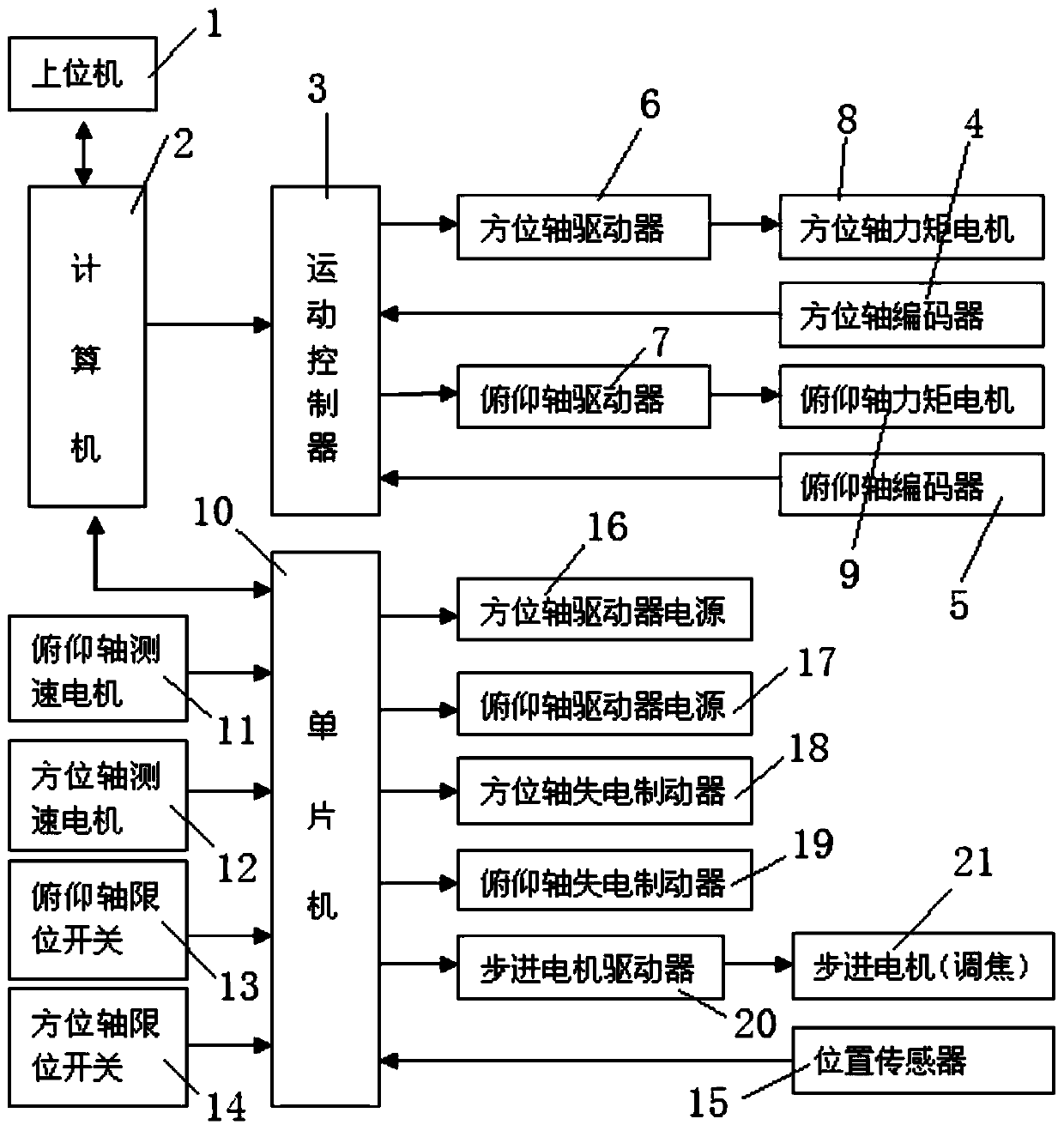
[0019] The principle block diagram of the rack control system is as follows: figure 1 As shown, a telescope rack control system includes a computer 2, a servo control system and a single-chip microcomputer control system, the servo control system includes a motion controller 3, and the signal input end of the motion controller 3 is connected to an azimuth axis encoder 4, a pitch axis Axis encoder 5, the signal output terminal of motion controller 3 is connected to azimuth axis driver 6 and pitch axis driver 7, and azimuth axis driver 6 and pitch axis driver 7 are connected to azimuth axis torque motor 8 and pitch axis torque motor 9 respectively; The control system includes a single-chip microcomputer 10, the signal input end of the single-chip microcomputer 10 is connected with a pitch axis speed measuring motor 11, an azimuth axis speed measuring motor 12, a pitch axis limit switch 13, an azimuth axis limit switch 14, a position sensor 15, and the signal output of the single ...


PUM


Abstract

The invention discloses a telescope frame control system. The signal input end of the motion controller is connected with the azimuth axis encoder and the pitch axis encoder, and the signal output end of the motion controller is connected with the azimuth axis driver, the pitch axis driver, and the azimuth axis driver. The pitch axis driver is connected to the torque motor of the azimuth axis and the torque motor of the pitch axis respectively; Position switch, position sensor, the signal output terminal of the microcontroller is connected to the power supply of the azimuth axis driver, the power supply of the pitch axis driver, the azimuth axis power-off brake, the pitch axis power-off brake, the stepper motor driver, the stepper motor driver is connected to the stepper motor, computer control Connect the motion controller and microcontroller. The invention effectively prevents failure caused by the azimuth axis and the pitch axis exceeding the range of motion, and ensures safe operation of the telescope.

Description

technical field [0001] The invention relates to the fields of control and electronics, in particular to a telescope frame control system. Background technique [0002] It is difficult for existing telescope systems to quickly track random moving targets, and a telescope system with faster speed, higher acceleration, and higher precision is required, and at the same time, it has perfect protection measures and a high degree of automation. Contents of the invention [0003] The invention provides a telescope frame control system, which solves the requirements for the speed, acceleration and precision of the telescope system. At the same time, multiple protections are designed to prevent system failure, and functions such as closed-loop focusing are designed. Specifically, it has the following functions: azimuth axis servo Control, pitch axis servo control, limit protection, stall protection, closed-loop focus control, etc. [0004] The technical scheme adopted in the presen...

Claims


Application Information

Patent Timeline
Patent Type & Authority Patents(China)
IPC IPC(8): G05D3/12
Inventor 谭逢富秦来安
Owner 安徽中科未来技术有限公司
Why Eureka
Try Eureka