

Thermoelectric conversion element and process for producing same
A technology of thermoelectric conversion and manufacturing method, which is applied in the manufacture/processing of thermoelectric devices, the material of the junction leads of thermoelectric devices, and the thermoelectric devices only using the Peltier or Seebeck effect, etc., and can solve the problems of reduction of electrical conductivity and Seebeck coefficient , to achieve the effect of excellent thermoelectric conversion performance
- Summary
- Abstract
- Description
- Claims
- Application Information
AI Technical Summary
Problems solved by technology
Method used
Image

Examples
manufacture example 1
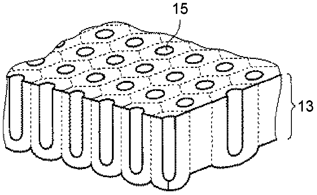
[0164] Production example 1 Production of anodized aluminum substrate (treatment liquid: sulfuric acid)
[0165] (A) Pretreatment (electrolytic grinding treatment)
[0166] A high-purity aluminum substrate (manufactured by Sumitomo Light Metals Co., Ltd., purity 99.99% by mass, thickness 0.4mm) is cut in an area of 10 cm square, so that anodic oxidation can be performed, and an electrolytic polishing solution with the following composition is used at a voltage of 25V and a liquid temperature of 65°C. The electrolytic grinding treatment was carried out under the condition of a liquid flow rate of 3.0 m / min.
[0167] The cathode was a carbon electrode, and GP0110-30R (manufactured by Takasago Seisakusho) was used as a power source. In addition, the flow velocity of the electrolytic solution was measured using a vortex flow monitor FLM22-10PCW (manufactured by AS ONE).
[0168] (Electrolytic polishing liquid composition)
[0169] ・85% by mass phosphoric acid (a reagent manuf...
manufacture example 2
[0180] Production Example 2 Production of anodized aluminum substrate (treatment liquid: oxalic acid)
[0181] (A) Pretreatment process (electrolytic polishing treatment)
[0182] It carried out similarly to (A) of manufacture example 1.
[0183] (B) Anodized film formation process (anodized treatment)
[0184] For the aluminum substrate obtained above after the electrolytic grinding treatment, anodizing treatment was performed for 1 hour under the conditions of a voltage of 40V, a liquid temperature of 15° C., and a liquid flow rate of 3.0 m / min using an electrolyte solution of 0.50 mol / L oxalic acid. Furthermore, the anodized sample was immersed in a 0.5 mol / L phosphoric acid aqueous solution at 40° C. for 25 minutes to perform a film removal treatment.
[0185] After repeating these treatments four times in this order, use an electrolyte solution of 0.50 mol / L oxalic acid to implement anodic oxidation treatment again for 4 hours under the conditions of voltage 40V, liquid...
Embodiment 1-1
[0188] Embodiment 1-1 Fabrication of thermoelectric conversion element
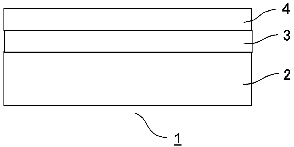
[0189] Using the sulfuric acid-treated anodized aluminum substrate obtained in Production Example 1, a thermoelectric conversion layer was formed by a sputtering method to fabricate a thermoelectric conversion element.
[0190] Made by In 2 o 3 : 90%-SnO 2 : A target material composed of 10% (ITO, purity: 4N) was formed into a film using a magnetron sputtering device. The film thickness of the thermoelectric conversion layer at this time was 150 nm.
[0191] The performance of the formed thermoelectric conversion layer was evaluated in the following manner. The results are shown in Table 1.
PUM
| Property | Measurement | Unit |
|---|---|---|
| melting point | aaaaa | aaaaa |
| pore size | aaaaa | aaaaa |
| melting point | aaaaa | aaaaa |
Abstract
Description
Claims
Application Information