Supercritical water heat combustion reactor for thick oil injection production

A supercritical water and reactor technology, applied in the field of energy and environment, can solve the problems of high material consumption, slow oxidation reaction speed, environmental pollution, etc., to overcome the problems of coking and salt deposition, reduce the viscosity of heavy oil, and have a broad market prospect Effect

Inactive Publication Date: 2014-07-02
TAIYUAN UNIV OF TECH
View PDF6 Cites 11 Cited by
  • Summary
  • Abstract
  • Description
  • Claims
  • Application Information

AI Technical Summary

Problems solved by technology

However, there are also certain problems in supercritical water oxidation technology.
First of all, the oxidation reaction speed is relatively slow, which generally takes several minutes, resulting in a long reactor, high material consumption, and high cost; secondly, crude oil is rich in a large amount of cycloalkanes and aromatic hydrocarbons, which are difficult to oxidize completely, which not only pollutes the environment, Moreover, resources are wasted; again, since the reaction can only be started when the supercritical condition is reached, the material needs to be preheated to the supercritical state in advance, which is easy to cause carbon precipitation, coking and salt deposition, which in turn leads to deterioration of heat transfer and blockage, causing safety accidents

Method used


Image

  • Supercritical water heat combustion reactor for thick oil injection production
  • Supercritical water heat combustion reactor for thick oil injection production
  • Supercritical water heat combustion reactor for thick oil injection production

Examples


Embodiment Construction

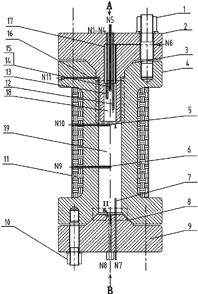
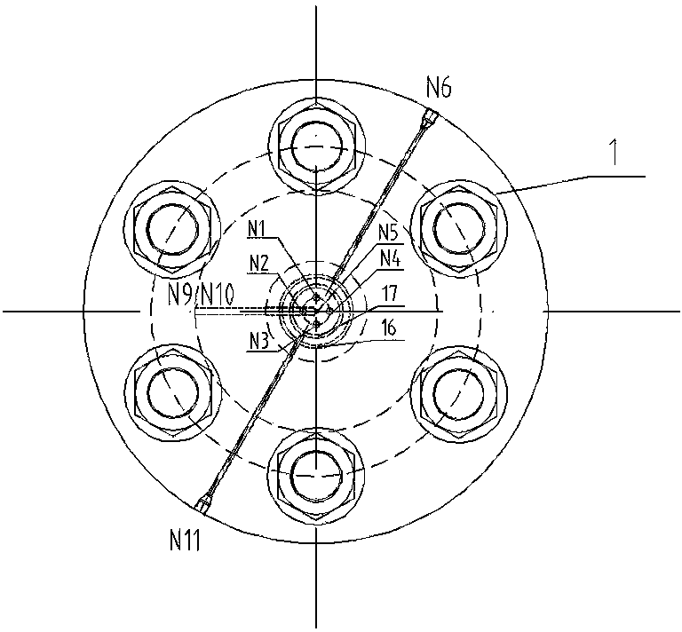
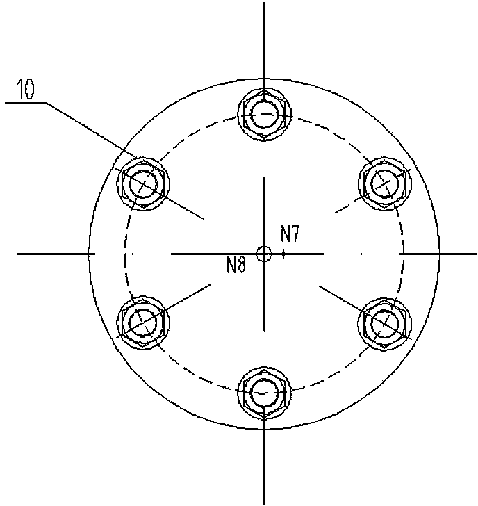
[0023] refer to Figure 1-Figure 5 , a supercritical hydrothermal combustion reactor for heavy oil injection and production, including an upper top cover 2 for bearing pressure, a reaction chamber 4 and a lower bottom cover 9, first nuts, bolts, gaskets 1 and 1 for sealing The second nut, bolt, gasket 10, and the first conical sealing surface 3 and the second conical sealing surface 8 are used to install the guide pipe 7 of the safety valve and pressure gauge, and the thermal insulation shell 11 for heat preservation is used for temperature measurement The first temperature measuring sleeve 5, the second temperature measuring sleeve 6 and the third temperature measuring sleeve 12~15, the annular groove 17 for introducing oxidant, the annular gap 16 for introducing supplementary water, and the upper top cover 2 The fuel inlet N5 arranged in the center, the thermocouple sockets N1~N4 arranged on the same circumference of the upper top cover 2 close to the fuel inlet N5, and the ...


PUM


Abstract

The invention belongs to the field of energy and environments, and particularly relates to a supercritical water heat combustion reactor for thick oil injection production. The supercritical water heat combustion reactor for thick oil injection production comprises a reaction chamber, an upper top cover and a lower bottom cover, wherein the reaction chamber is hollow, openings are formed in the upper end and the lower end of the reaction chamber respectively, the upper top cover is connected with the opening formed in the upper end of the reaction chamber in a sealed mode, the lower bottom cover is connected with the opening formed in the lower end of the reaction chamber, and a closed space is formed by the reaction chamber, the upper top cover and the lower bottom cover; a cylindrical stepped hollow portion is formed in the center of the upper top cover, a stepped hollow portion on the lower portion of the cylindrical stepped hollow portion serves as a combustor, a stepped hollow portion on the upper portion of the cylindrical stepped hollow portion serves as a communicated fuel inlet, an annular groove is formed in the outer side of the lower end of the stepped hollow portion on the upper portion of the cylindrical stepped hollow portion, the lower portion of the annular groove is communicated with the combustor, and the annular groove is communicated with an oxidizing agent inlet formed in the side face of the upper top cover; a mixing chamber is arranged at the bottom of the combustor, an annular gap formed between the upper top cover and the reaction chamber is formed in the side of the combustor, and the annular gap is communicated with a supplementary water inlet formed in the side face of the reaction chamber.

Description

[0001] Technical field [0002] The invention belongs to the field of energy and environment, in particular to a supercritical hydrothermal combustion reactor used for heavy oil injection and production. Background technique [0003] Due to the high viscosity, there are great difficulties in the production and transportation of heavy oil. To solve this problem, steam injection boilers are often used in heavy oil fields to generate steam for thermal recovery, which has become an effective means of heavy oil recovery. But this not only consumes a large amount of steam, but also produces a large amount of oil production waste liquid. Oil production waste liquid contains a large amount of crude oil. If it is discharged into the environment, it will not only cause serious environmental pollution, but also cause waste of resources; if it is recycled by heat, the treatment cost of waste liquid will be as high as 7 yuan / m 3 Even so, the heat recovery of waste liquid is still very ...

Claims


Application Information

Patent Timeline
Patent Type & Authority Applications(China)
IPC IPC(8): F23G7/04E21B43/24
Inventor 马红和周璐马素霞赵泽青
Owner TAIYUAN UNIV OF TECH
Why Eureka
Try Eureka