Medical suture thread friction performance test device and test method
A friction performance and testing device technology, which is applied in the direction of measuring devices, mechanical devices, instruments, etc., can solve the problems of high cost, small difference in yarn friction coefficient, complicated experiments, etc., and achieve simple structure and improved reproducibility Effect
- Summary
- Abstract
- Description
- Claims
- Application Information
AI Technical Summary
Problems solved by technology
Method used
Image
Examples
Embodiment 1
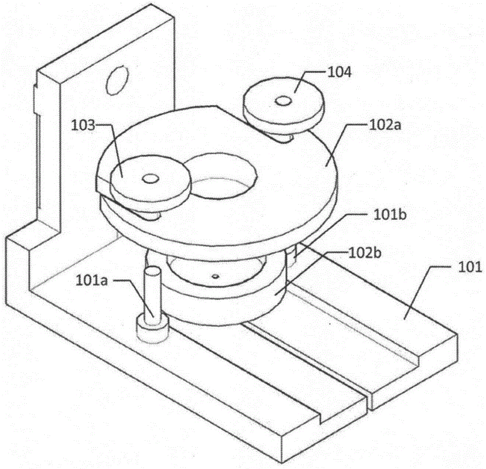
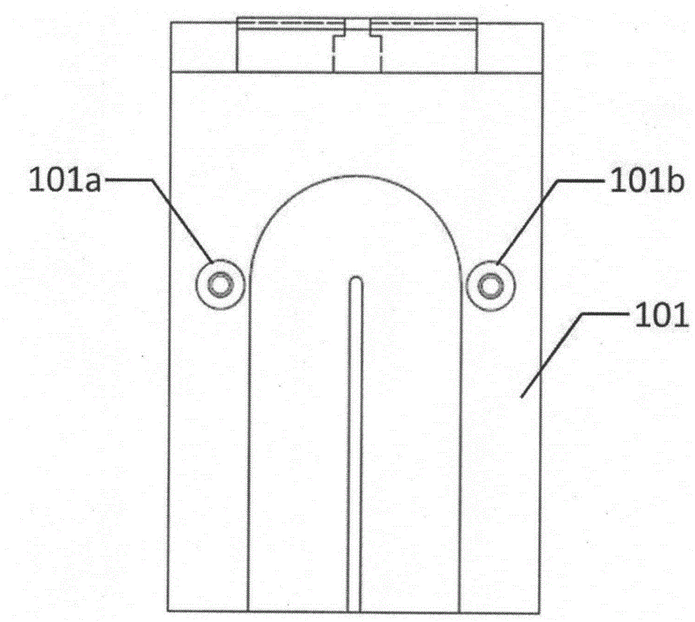
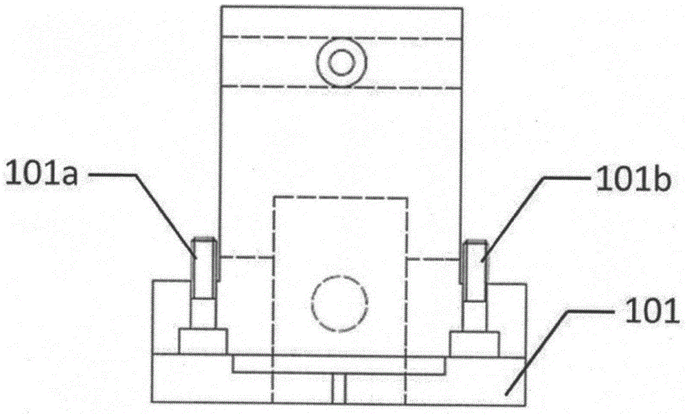
[0051] This example uses as figure 1 The shown friction performance test assembly when the medical suture thread penetrates the tissue includes a part fixing seat 101 and a tissue clamping part. combine Figure 3A-1 , Figure 3A-2 , Figure 3B-1 and Figure 3B-2 , the tissue clamping parts include a cloth clamping round cover 102a and a base 102b for placing a simulated tissue for simulating human epidermis, the cloth clamping round cover 102a has a presser foot, and the diameter of the presser foot is the same as the inner wall diameter of the base 102b, and There are circular holes with a diameter of 2mm at the center of the circle respectively. The cloth-clad round cover 102a and the base 102b can be nested with each other, and the positions of the circular holes coincide after nesting, and the two holes can be connected. The nested tissue clamping parts can be assembled in the slot of the fixing base 101 through the nut 103 and the nut 104, wherein the nuts 103 and 10...
Embodiment 2
[0055] The testing device of this embodiment is the same as that of Embodiment 1.
[0056] In the tissue clamping part, the diameter of the presser foot of the cloth clamping round cover 102a is the same as that of the inner wall of the base 102b, and there are round holes with a diameter of 15mm at the center of the circle respectively. The two can be nested with each other, and the positions of the round holes coincide after nesting , two holes can pass through. The nested tissue clamping parts can be assembled in the slot of the fixing base 101 through the nut 103 and the nut 104 , wherein the nut 103 and the nut 104 cooperate with the screw 101a and the screw 101b respectively. There is a slit with a diameter of 15 mm on the central axis of the base part of the fixing seat 101, and the slit is connected with the round hole of the cloth-clamping round cover 102a and the base 102b of the tissue clamping part assembled in the slot.
[0057] In this embodiment, a skin-like no...
Embodiment 3
[0060] The specifications of the test device and clamping parts of this embodiment are the same as those of Embodiment 1.
[0061] In this embodiment, a commercially available artificial skin dermis is used to simulate tissue, which is cut into a circle with the same diameter as the inner wall of the base 102b, and placed in the base 102b. nesting. The nested tissue clamping part 102 is placed in the slot of the fixing seat 101, the screw 101a and the screw 101b respectively pass through the U-shaped groove of the cloth clamping round cover 102a, and the nut 103 and the nut 104 respectively connect with the screw 101a and the screw 101a. 101b is tightened. 2-0 # Specification Silk medical suture length is 10cm, one end is connected with 40cN load, and the other end is connected with suture needle. The suture needle vertically passes through the round hole of the cloth clamping round cover 102a of the tissue clamping part, the simulated tissue, and the round hole of the base...
PUM
| Property | Measurement | Unit |
|---|---|---|
| diameter | aaaaa | aaaaa |
| width | aaaaa | aaaaa |
| friction | aaaaa | aaaaa |
Abstract
Description
Claims
Application Information
 - R&D
- Intellectual Property
- Life Sciences
- Materials
- Tech Scout
- Unparalleled Data Quality
- Higher Quality Content
- 60% Fewer Hallucinations
Browse by: Latest US Patents, China's latest patents, Technical Efficacy Thesaurus, Application Domain, Technology Topic, Popular Technical Reports.
© 2025 PatSnap. All rights reserved.Legal|Privacy policy|Modern Slavery Act Transparency Statement|Sitemap|About US| Contact US: help@patsnap.com


