Micro-flow detector based on SERS (Surface Enhanced Raman Scattering) principle and preparation method thereof
A detector and microfluidic technology, applied in the direction of Raman scattering, material excitation analysis, etc. It takes several hours or even longer to solve the problem, the distribution cannot achieve good uniformity, and affects the consistency of Raman scattering signals In order to achieve controllable detection speed, save detection time, and shorten detection time
- Summary
- Abstract
- Description
- Claims
- Application Information
AI Technical Summary
Problems solved by technology
Method used
Image

Examples
preparation example Construction
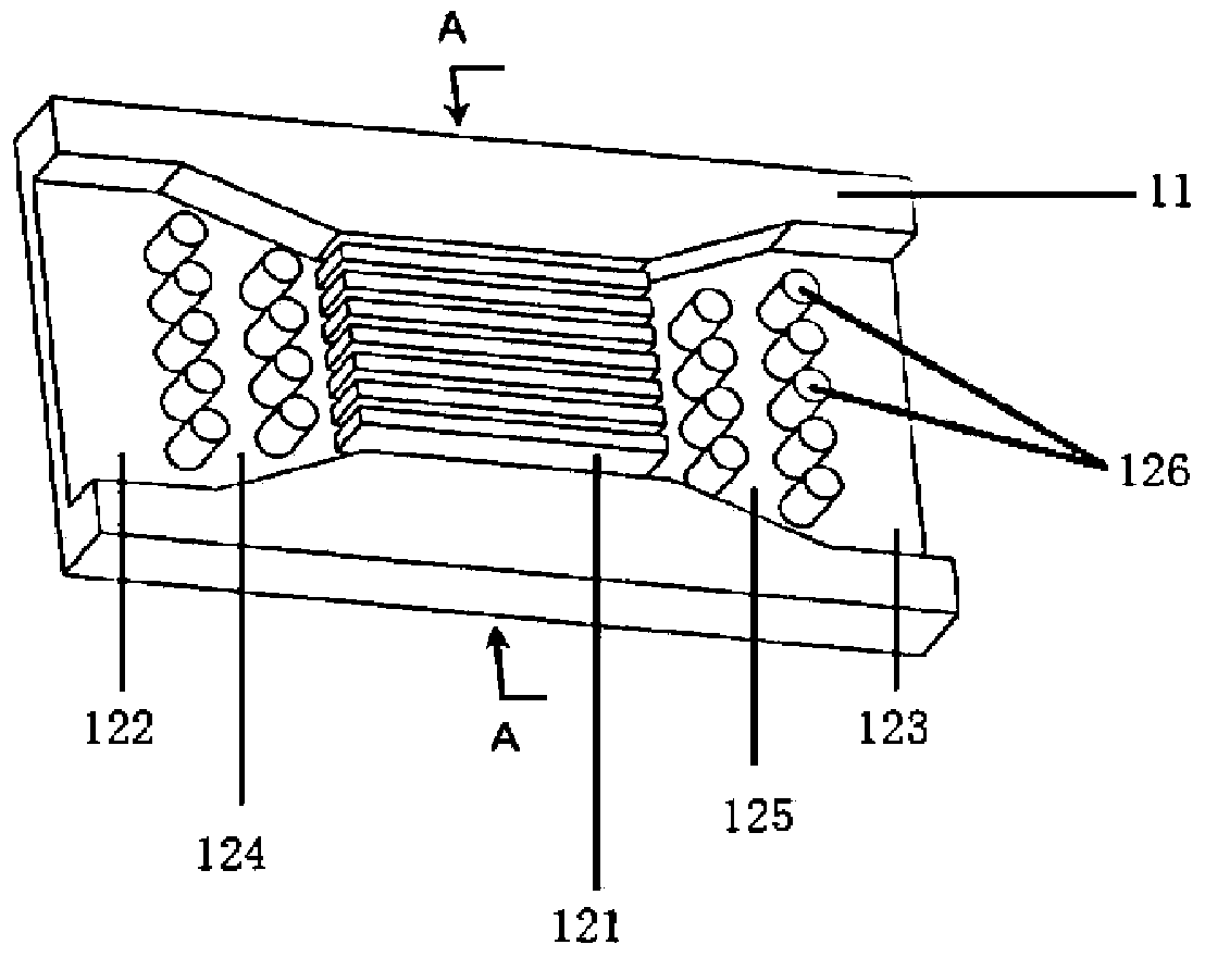
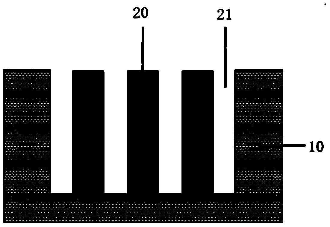
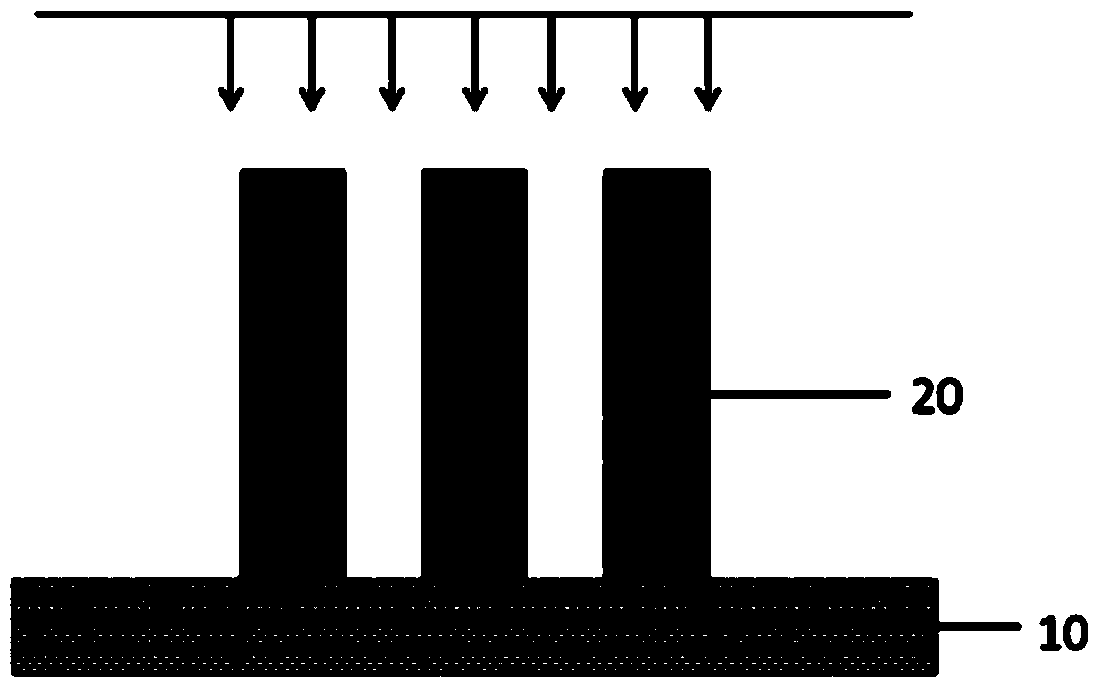
[0049] According to another aspect of the present invention, also provide a kind of preparation method of the microflow detector based on SERS mechanism, such as Figures 5a-5h shown. The preparation method includes the following steps: step S1, setting the substrate 10 and forming a groove on the upper surface 11 of the substrate 10; step S2, engraving a grating structure pattern in the groove; and step S3, depositing metal in the grating structure pattern to A metal grating 20 is formed; the metal grating 20 defines a plurality of micro-channels 21 of the groove through which the substance to be measured passes. The preparation method is simple, does not require large instruments and equipment, and is suitable for large-scale production.
[0050] Such as Figures 5a-5c As shown, specifically, the step of forming a groove on the upper surface 11 of the substrate 10 in step S1 includes: step S11, coating an ultraviolet photoresist layer 14 on the upper surface 11 of the subs...
Embodiment 1
[0056] 1) Take a clean Si substrate as a base, and spin-coat an ultraviolet photoresist layer on the upper surface of the Si substrate, wherein the thickness of the ultraviolet photoresist layer is 1.5 μm.
[0057] 2) Exposing and developing the ultraviolet photoresist layer to form a groove pattern to be etched on the substrate, and etching the groove pattern to be etched by reactive ion beam etching to form a groove pattern on the upper surface of the substrate Trench with a depth of 500nm.
[0058] 3) Spin-coat electron beam photoresist in the groove with a thickness of 600nm; use electron beam exposure and development technology to process the electron beam photoresist to form a grating structure pattern; Metal Au is deposited, and a linear grating composed of multiple Au flakes is obtained in the detection area. The Au grating is flush with the upper surface of the substrate, with a period of 200 nm and a duty ratio of 0.2.
[0059] The other parts of the trench are proc...
Embodiment 2
[0062] 1) Take a clean Si substrate as a base, and spin-coat an ultraviolet photoresist layer on the upper surface of the Si substrate, wherein the thickness of the ultraviolet photoresist layer is 1.5 μm.
[0063] 2) Exposing and developing the ultraviolet photoresist layer to form a groove pattern to be etched on the substrate, and etching the groove pattern to be etched by reactive ion beam etching to form a groove pattern on the upper surface of the substrate Trench with a depth of 500nm.
[0064] 3) Spin-coat electron beam photoresist in the groove with a thickness of 600nm; use electron beam exposure and development technology to process the electron beam photoresist to form a grating structure pattern; Metal Au is deposited, and a linear grating composed of multiple Au flakes is obtained in the detection area. The vertical height x of the Au grating protruding from the upper surface of the substrate is 500nm, the period is 900nm, and the duty ratio is 0.7.
[0065] The...
PUM
| Property | Measurement | Unit |
|---|---|---|
| Depth | aaaaa | aaaaa |
| Depth | aaaaa | aaaaa |
| Diameter | aaaaa | aaaaa |
Abstract
Description
Claims
Application Information
 - R&D
- Intellectual Property
- Life Sciences
- Materials
- Tech Scout
- Unparalleled Data Quality
- Higher Quality Content
- 60% Fewer Hallucinations
Browse by: Latest US Patents, China's latest patents, Technical Efficacy Thesaurus, Application Domain, Technology Topic, Popular Technical Reports.
© 2025 PatSnap. All rights reserved.Legal|Privacy policy|Modern Slavery Act Transparency Statement|Sitemap|About US| Contact US: help@patsnap.com