Steam-bubble-driven micro pump conducting heating through induction

A technology of induction heating and bubbles, which is applied to pumps, parts of pumping devices for elastic fluids, pump components, etc., can solve the problems of large pumping flow rate and difficult processing and production, and achieve large flow output and reduce Pollution sources and mechanical failures, the effect of achieving flow output

Active Publication Date: 2014-08-06
湖州南浔双程建设发展有限公司
View PDF6 Cites 24 Cited by
  • Summary
  • Abstract
  • Description
  • Claims
  • Application Information

AI Technical Summary

Problems solved by technology

[0003] The purpose of the present invention is to overcome the shortcomings of the traditional resistance heating bubble pump, such as the difficulty in realizing large p

Method used


Image

  • Steam-bubble-driven micro pump conducting heating through induction
  • Steam-bubble-driven micro pump conducting heating through induction
  • Steam-bubble-driven micro pump conducting heating through induction

Examples


Embodiment Construction

[0060] specific implementation plan

[0061] Micropump processing technology of the present invention is made, embodiment one

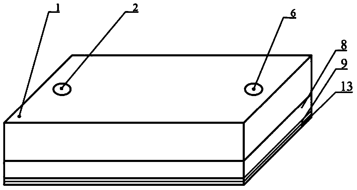
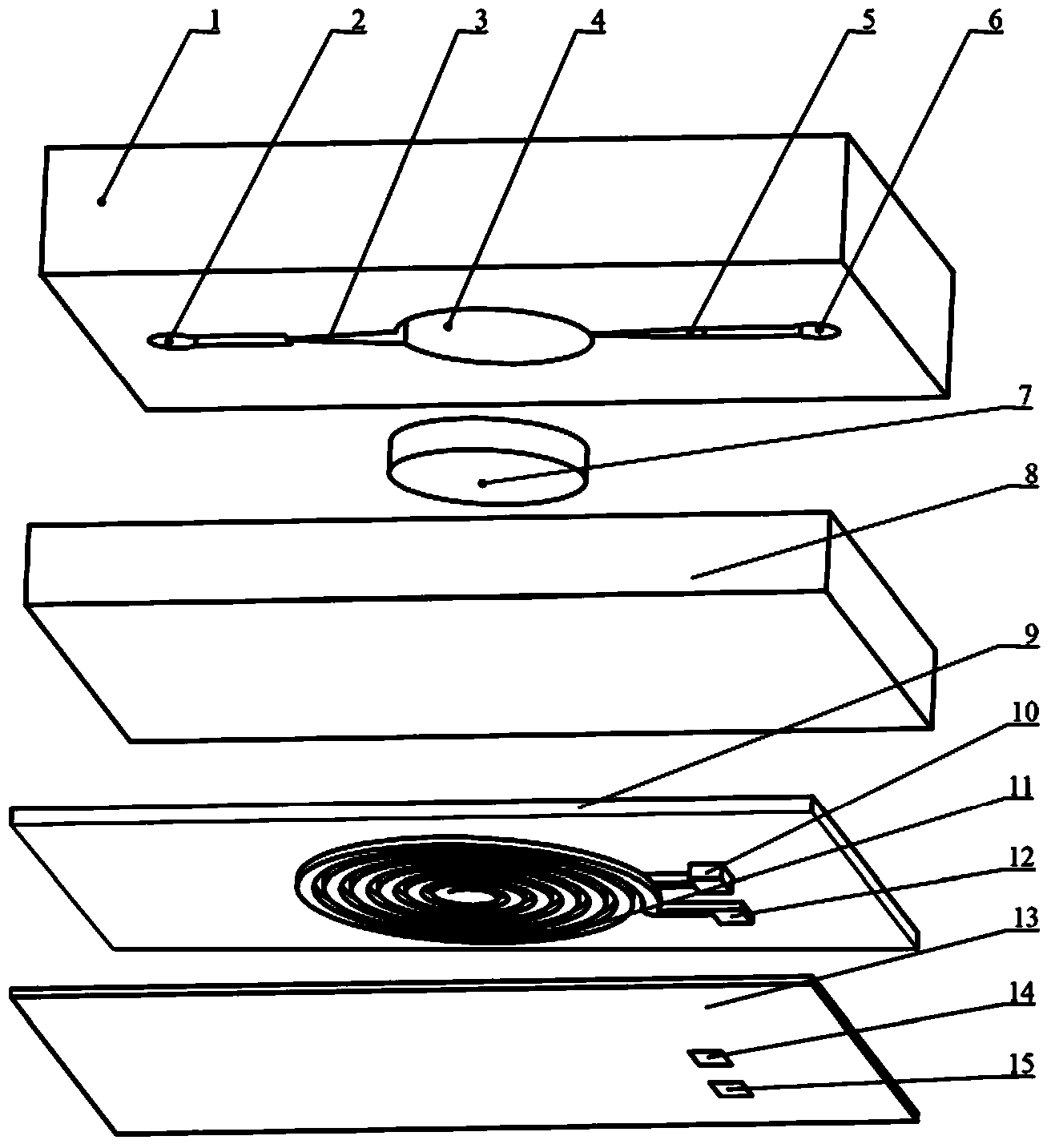
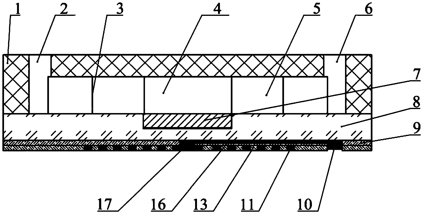
[0062] The microfluidic upper chip 1 in the present invention adopts SU-8 negative photoresist to make a positive mold, and polydimethylsiloxane (PDMS) injection molding process is used for manufacturing. The specific process flow is as follows:

[0063] (a) with Figure 14 , select silicon substrate I20 as the substrate, wash it with deionized water, and dry it on a rubber drying table at a temperature of 110°C;

[0064] (b) with Figure 15 , Spin coat a layer of SU-8 glue 21 on the silicon substrate I20, the thickness of the glue layer is 50μm-250μm, use a hot plate for pre-baking, first dry at a temperature of 65°C for 35min, and then bake at a temperature of 95°C The drying time is 30-90 minutes (related to the thickness of the adhesive layer, the greater the thickness, the longer the drying time), and then naturally cool to solidify the SU-8 a...


PUM

PropertyMeasurementUnit
Diameteraaaaaaaaaa
Depthaaaaaaaaaa
Thicknessaaaaaaaaaa

Abstract

The invention discloses a steam-bubble-driven micro pump conducting heating through induction, and belongs to the field of micro-flow control systems. A pump body is composed of a micro-flow-control upper chip (1), a heating disk (7), a glass base (8) and a magnet exciting coil (11). The micro-flow-control upper chip (1) structurally comprises a liquid inlet (2), a micro flow channel I (3), a micro cavity (4), a micro flow channel II (5) and a liquid outlet (6). According to the micro pump, liquid in the micro cavity (4) is heated through induction eddy currents to enable the liquid to be partially vaporized to generate steam bubbles, the micro pump is driven through pressure pulses generated at the moment when the steam bubbles expand to become large, and the function of pumping a micro amount of liquid can be realized. No movable components exist in the micro pump, so that pollution sources and mechanical faults are reduced, meanwhile, the micro pump has the advantages of being high in flow and controllable, and the micro pump has wide application prospects in various fields such as disease diagnosing, medicine conveying, fuel feeding and environment detection.

Description

technical field [0001] The present invention is an induction-heated bubble-driven micropump, specifically a valveless micropump driven by bubbles that uses electromagnetic induction to heat liquid to vaporize part of the liquid, and can pump trace amounts of liquid. function. The micro-bubble pump is an important part of the microfluidic system. It has broad application prospects in various fields such as disease diagnosis, drug delivery, fuel supply, and environmental detection. It belongs to the field of microfluidic systems. Background technique [0002] At present, most micro-bubble pumps are driven by resistive thermal bubbles. In 2002, Jr-Hung Tsai and Lin Liwei of the University of California, Berkeley developed a thermal bubble-driven micropump that is easy to integrate. The micropump uses a resistance heater made of aluminum wires to heat the liquid. In 2007, Korean scholar Jung-Yeul Jung developed a thermal bubble pump using polysilicon as a heating resistor. Ta...

Claims


Application Information

Patent Timeline
IPC IPC(8): F04B19/24F04B53/08
Inventor 刘本东候岳鹏
Owner 湖州南浔双程建设发展有限公司
Why Eureka
Try Eureka