Pyrolysis furnace and treatment process for treating waste tire

A pyrolysis furnace and waste tire technology, applied in coking ovens, petroleum industry, recycling technology, etc., can solve the problems of reducing system thermal efficiency, easy leakage of rotating parts and static parts, and non-continuous operation, so as to avoid instability, Uniform heating, highlighting the effect of substantive features

Inactive Publication Date: 2014-08-13
ENERGY RES INST OF SHANDONG ACAD OF SCI
View PDF7 Cites 15 Cited by
  • Summary
  • Abstract
  • Description
  • Claims
  • Application Information

AI Technical Summary

Problems solved by technology

This will consume a large amount of pyrolytic carbon products, and in the cooling process of mineral oil vapor, accompanied by the cooling of a large amount of circulating carrier gas, the thermal efficiency of the system will be reduced, and the heating surface and investment of cooling equipment will be increased.
This avoids the above-mentioned problems in indirect heating technology. Indirect heating technology generally adopts horizontal rotary equipment for production, as described in patents such as application numbers 201010223429.9 and 200610053685.1. There are problems such as easy leakage of harmful gases in the gaps between components, and some indirect heating processes cannot even run continuously, which is the deficiency of the existing technology

Method used


Image

  • Pyrolysis furnace and treatment process for treating waste tire
  • Pyrolysis furnace and treatment process for treating waste tire
  • Pyrolysis furnace and treatment process for treating waste tire

Examples


Embodiment Construction

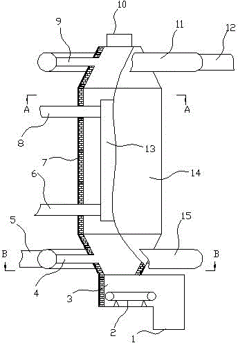
[0025] In order to clearly illustrate the technical characteristics of this scheme, the following is a detailed description of this scheme through a specific implementation method with a processing capacity of 100 kg per hour for waste tires, combined with its accompanying drawings.

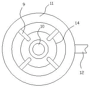
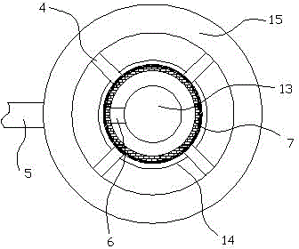
[0026]As can be seen from the accompanying drawings, the pyrolysis furnace for pyrolytic treatment of waste tires in this program includes a furnace body 14 with a furnace lining 7, a feed port 10 and a discharge port 1, and the furnace body 14 is made of Q235 carbon The shell made of steel plate is composed of the furnace lining 7 made of aluminum silicate refractory fiber felt and high alumina refractory bricks. The furnace body 14 described in this program is cylindrical, and the ratio of the height to the outer diameter of the furnace body 14 is 2.0-4.0. In this specific embodiment, the outer diameter of the furnace body 14 is 0.9 meters, and the height of the furnace body 14 is 3.6 meters. T...


PUM


Abstract

The invention provides a technical scheme of a pyrolysis furnace and a treatment process for treating waste tires. According to the technical scheme, the upper and lower parts of a furnace body take the shapes of columns of trapezoidal cones; a feeding hole is formed in the top side of the furnace body; a discharge hole is formed in the bottom side of the furnace body; an annular exhaust surrounding tube is arranged on the outer side of the upper conical part of the furnace body; a main exhaust tube is connected to the outer side wall of the exhaust surrounding tube; a plurality of branch exhaust tubes are connected to the inner side wall of the exhaust surrounding tube and are communicated with an inner cavity of the furnace body; an annular inlet surrounding tube is arranged on the outer side of the lower conical part of the furnace body; a main inlet tube is connected to the outer side wall of the inlet surrounding tube; a plurality of branch inlet tubes are connected to the inner side wall of the inlet surrounding tube and are communicated with the inner cavity of the furnace body; the furnace body is internally provided with an inner heating tube with an inner thermal gas inlet tube and an inner thermal gas exhaust tube. The treatment process of the scheme comprises the following steps: performing pyrolysis on waste tire fragments by using the pyrolysis furnace, obtaining crushed steel wires and finished carbon black product from pyrolysis slag after pyrolysis, obtaining heavy oil and a finished slag oil product from a pyrolysis gas by using a cyclone separator and a spraying tower, further obtaining a finished light oil product by using a pipe bundle condenser, heating the rest pyrolysis gas by using a combustion furnace, and subsequently feeding back to the pyrolysis furnace to provide high-temperature fume.

Description

technical field [0001] The invention relates to equipment and technology for treating and utilizing waste containing high-molecular organic matter, in particular to a pyrolysis furnace for treating waste tires and a processing technology. Background technique [0002] In the prior art, the waste tire pyrolysis process can be divided into direct heating technology and indirect heating technology. The direct heating technology, as described in patent application numbers 200680054973.7, 200980140238.1 and 200980137677.7, uses the flue gas after pyrolysis charcoal combustion to heat the inert circulation carrier gas first, and then directly contacts the high-temperature inert circulation carrier gas with waste tires for pyrolysis. This will consume a large amount of pyrolytic carbon products, and in the cooling process of mineral oil vapor, accompanied by the cooling of a large amount of circulating carrier gas, the thermal efficiency of the system will be reduced, and the heati...

Claims


Application Information

Patent Timeline
Patent Type & Authority Applications(China)
IPC IPC(8): C10B53/07C10G1/10C09C1/54B29B17/02
CPCY02P20/129Y02P20/143Y02W30/62
Inventor 王凯孙荣峰范晓旭关海滨姜建国张卫杰
Owner ENERGY RES INST OF SHANDONG ACAD OF SCI
Why Eureka
Try Eureka