Method for manufacturing solar cell positive electrode grid line

A technology of solar cells and positive electrodes, which is applied in circuits, photovoltaic power generation, electrical components, etc., can solve the problems of increased grid line width, improvement, and unfavorable cell efficiency, etc., and achieves low series resistance, simple process, and ideal shape of the seed layer Effect

Active Publication Date: 2014-08-20
CECEP SOLAR ENERGY TECH (ZHENJIANG) CO LTD
View PDF7 Cites 4 Cited by
  • Summary
  • Abstract
  • Description
  • Claims
  • Application Information

AI Technical Summary

Problems solved by technology

If silver plating is performed directly on the printed and sintered grid lines, there will be a situation where silver is also plated on the

Method used


Image

  • Method for manufacturing solar cell positive electrode grid line
  • Method for manufacturing solar cell positive electrode grid line
  • Method for manufacturing solar cell positive electrode grid line

Examples


Embodiment 1

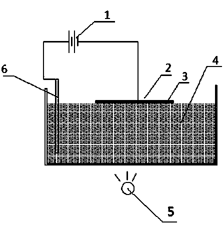
[0020] Embodiment 1: A kind of preparation method of solar cell positive electrode grid line, specific process is:

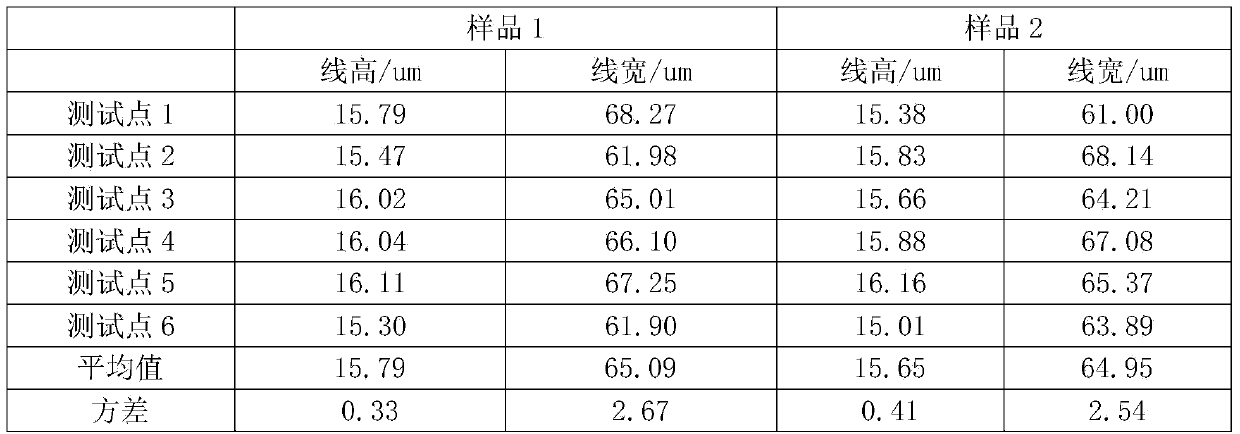
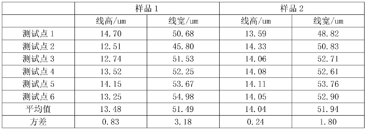
[0021] a. On the silicon wafer that has undergone previous processes such as texturing, diffusion, edge insulation, PSG removal, and anti-reflection coating, and has printed the back electrode and the back electric field, screen-print the positive electrode grid line and sinter it quickly to form an ohmic Contact; specifically, the screen parameters used in screen printing are: the number of fine grid lines is 88, the mesh is 360 mesh, the opening of the fine grid lines is 36um, the wire diameter is 16um, and the thickness of the photosensitive film is 15um; It is 80mg of silver paste dedicated to the positive electrode of solar cells, and it is required that there is no broken grid after printing. The line height and line width after sintering are shown in the following table:

[0022] Table 1 Line height and line width of grid lines after sintering

[0023] ...

Embodiment 2

[0039] Example 2: roughly the same as Example 1, the difference is that the amount of silver paste printed in step a is 60mg; the applied voltage in step b is 1.5V, the light intensity is 6000lux, the reaction temperature is 20°C, the reaction time is 5min, the dissolution of the positive electrode The amount is 15 mg; the light intensity in step c is 6000 lux, the reaction temperature is 20° C., and the amount of silver plating on the positive electrode is 20 mg.

Embodiment 3

[0040] Example 3: roughly the same as Example 1, the difference is that the amount of silver paste printed in step a is 100mg; the applied voltage in step b is 2V, the light intensity is 15000lux, the reaction temperature is 60°C, the reaction time is 10min, and the amount of positive electrode dissolved is 30 mg; in step c, the light intensity is 15000 lux, the reaction temperature is 60° C., and the amount of silver plating on the positive electrode is 50 mg.


PUM

PropertyMeasurementUnit
Widthaaaaaaaaaa

Abstract

The invention discloses a method for manufacturing a solar cell positive electrode grid line. Through the wool manufacturing, diffusion, edge insulation, PSG removing and reflecting film plating and reducing technology, a positive electrode grid line graph is printed on a silicon wafer in a silk-screen mode, the silicon wafer is printed with a back electrode and a back electric field, rapid sintering is performed to form ohmic contact, a sintered cell piece is placed in a light induction plating tank, the cell piece is taken as a positive electrode, a silver stick is taken as a negative electrode, part of the grid line is dissolute to be manufactured into a seed layer, light induction plating is adopted, silver plating and thickening are performed on the seed layer, the silk-screen printing technology and rapid sintering technology are adopted on a solar positive electrode to form the good ohmic contact, on the basis of the grid line graph with the qualified tensile force, plating dissolving is performed on the deckle edge area of the grid line, the width of the grid line cannot be increased due to the deckle edge, afterwards, silver is electroplated on the grid line, and the cross section of the manufactured grid line is quasi-semi-circular. The line width is small, the depth-width ratio is large, the seed layer form is ideal, the grid line structure is compact, the series resistance is low, and the conversion efficiency of a cell piece can be effectively improved.

Description

technical field [0001] The invention relates to the field of solar cell manufacturing technology, in particular to a method for preparing positive electrode grid lines. Background technique [0002] With the increasing tension of global energy sources, solar cells have unique advantages such as no pollution, no mechanical rotating parts, easy maintenance, unattended, short construction period, random scale, easy combination with buildings, and large market space. The advantages have been widely valued by countries all over the world, and many large companies in the world have invested in the research and development and production of solar cells. Currently, the challenge in manufacturing silicon solar cells is to improve the efficiency of solar cells to increase the power generation per unit area, and to further reduce the manufacturing cost so that it can be widely used. In crystalline silicon solar cells, the preparation of the positive electrode grid on the silicon wafer...

Claims


Application Information

Patent Timeline
IPC IPC(8): H01L31/18H01L31/0224
CPCH01L31/022433H01L31/022441Y02E10/50Y02P70/50
Inventor 黄钧林勾宪芳范维涛周肃黄青松黄惜惜
Owner CECEP SOLAR ENERGY TECH (ZHENJIANG) CO LTD
Why Eureka
Try Eureka