Frequency-control wave beam/focal point scanning plane reflective array/reflector

A frequency control, scanning plane technology, applied in electrical components, antennas, etc., can solve the problems of scanning array cost, loss design complexity, etc., and achieve the effect of shortening simulation time, convenient processing, and speeding up simulation speed

Inactive Publication Date: 2014-09-03
UNIV OF ELECTRONICS SCI & TECH OF CHINA
View PDF3 Cites 23 Cited by
  • Summary
  • Abstract
  • Description
  • Claims
  • Application Information

AI Technical Summary

Problems solved by technology

[0010] In view of the above-mentioned technical background, in order to solve the cost, loss and design complexity of the current scanning array, the present invention propos...

Method used


Image

  • Frequency-control wave beam/focal point scanning plane reflective array/reflector
  • Frequency-control wave beam/focal point scanning plane reflective array/reflector
  • Frequency-control wave beam/focal point scanning plane reflective array/reflector

Examples


Embodiment Construction

[0035] The technical solution of the present invention will be described in detail below in conjunction with the accompanying drawings, mainly divided into two parts, but the protection scope of the present invention is not limited to the implementation examples.

[0036] Part 1: Frequency-controlled electronically scanned planar reflectarray antenna

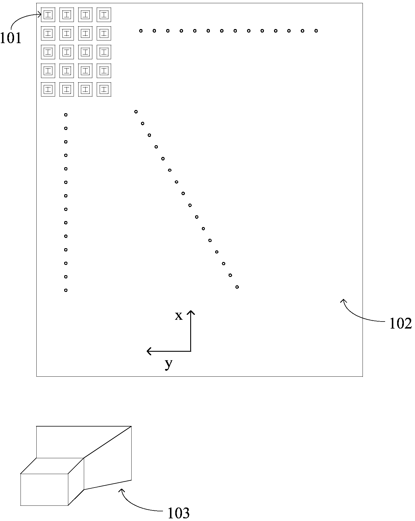
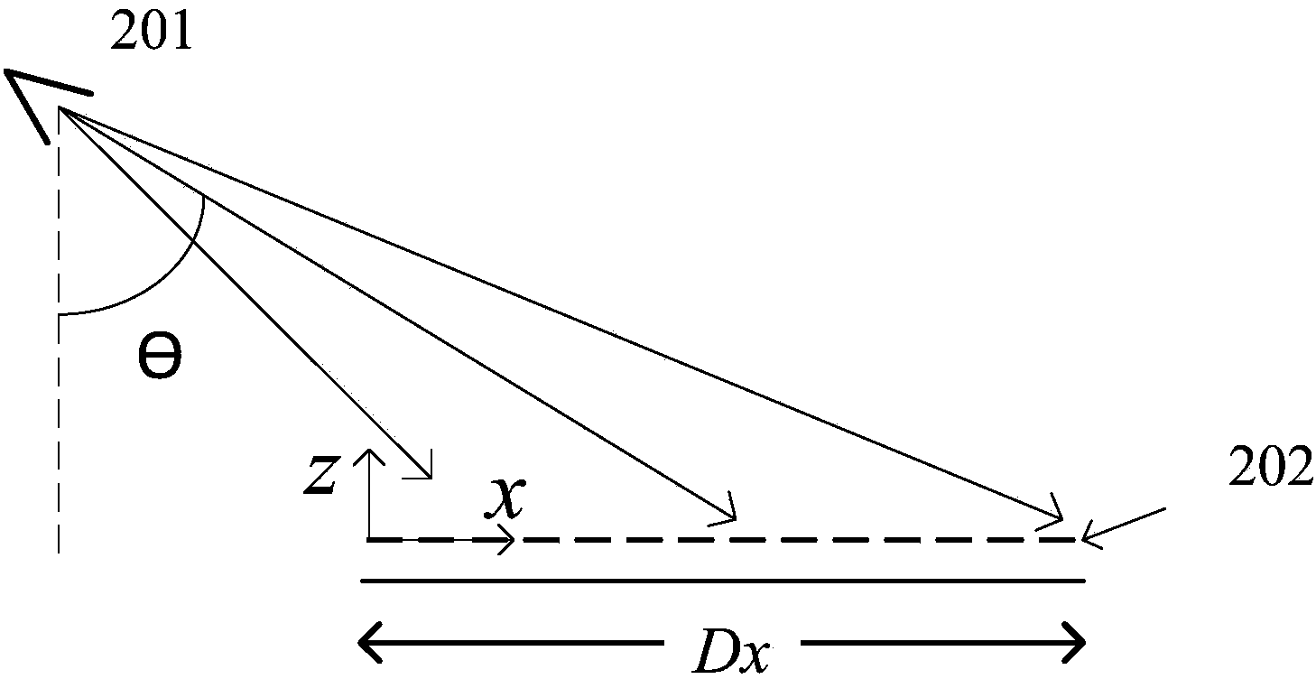
[0037] figure 1 and figure 2 An example of frequency-controlled electronically scanned planar reflectarray is described. figure 1 It is a schematic diagram of the 50×40 array used in the implementation process. The printed patch array 102 is composed of 2000 radiation elements 101 to form the planar reflection array, and the pyramid horn 103 feeds it. The overall example picture is as follows figure 2 As shown, the feed horn 201 feeds the reflective array 202 . Here, the incident angle is selected as 50°, corresponding to the coordinate axes in the figure, the phase center position of the horn is x=-30, z=27, y=0, and the ...


PUM


Abstract

The invention discloses a frequency-control wave beam/focal point scanning plane reflective array/reflector. The basic structure of the plane reflective array and the basic structure of the reflector respectively comprise a printed patch array, a primary feed source and a corresponding supporting structure. The plane reflective array is irradiated by spherical waves, focusing of wave beams is realized in a far field, and the plane reflective array can be used in a modern wireless communication system and a modern radar system. The reflector is irradiated by plane waves or cylindrical waves or spherical waves, can realize wave beam focusing in a near field and can be applied to an imaging system. The plane reflective array and the reflector respectively enable the phase value actually obtained on each frequency point to meet the theoretically required value through selection of the size and freedom degree parameters of each unit, therefore, in-phase superposition, in different directions, of the array at different frequency points is realized, and the function of wave beam or focal point scanning is achieved. The frequency-control wave beam/focal point scanning plane reflective array/reflector has the advantages that electric wave beam/focal point scanning and high gain are realized through the simple array surface structure, and the cost, the loss and the complexity of a current scanning array/imaging system are greatly reduced.

Description

technical field [0001] The invention belongs to the fields of wireless communication technology, radar technology and imaging technology, and in particular relates to an electrically scanning planar reflective array antenna and reflector which can effectively reduce the cost and complexity of a beam scanning array / imaging system, and is suitable for communication, radar or imaging systems middle. Background technique [0002] With the rapid development of contemporary communication technologies, antennas with focused beams play an increasingly important role. Traditional focused beam antennas mainly include parabolic reflectors and array antennas. For parabolic antennas, the fuselage is heavy and bulky, and the special curved surface is difficult to manufacture. In higher frequency bands, due to the shorter wavelength of electromagnetic waves, the processing accuracy The higher requirements make the processing difficulty more obvious. In addition, it is also difficult to a...

Claims


Application Information

Patent Timeline
IPC IPC(8): H01Q15/14
Inventor 屈世伟吴伟伟易欢白雪夏润梁蒋琪
Owner UNIV OF ELECTRONICS SCI & TECH OF CHINA
Why Eureka
Try Eureka