Redox flow secondary battery and electrolyte membrane for redox flow secondary battery

一种二次电池、电解质膜的技术,应用在固体电解质、非水电解质、固体电解质燃料电池等方向,能够解决降低电阻、隔膜易于氧化等问题

Inactive Publication Date: 2014-09-10
ASAHI KASEI KK
View PDF21 Cites 12 Cited by
  • Summary
  • Abstract
  • Description
  • Claims
  • Application Information

AI Technical Summary

Problems solved by technology
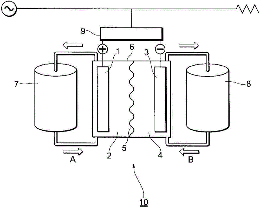
However, existing separators have problems such as being prone to oxidation, and it is necessary to sufficiently reduce resistance.

Method used


Image

  • Redox flow secondary battery and electrolyte membrane for redox flow secondary battery
  • Redox flow secondary battery and electrolyte membrane for redox flow secondary battery
  • Redox flow secondary battery and electrolyte membrane for redox flow secondary battery

Examples


Embodiment 1

[0404] (1) Manufacture of PFSA resin precursor

[0405] Put C into a stainless steel stirred autoclave 7 f 15 COONH 4 10% aqueous solution and pure water, after sufficient vacuum nitrogen replacement, introduce tetrafluoroethylene (CF 2 = CF 2 ) (hereinafter also referred to as "TFE") gas, pressurized to a gauge pressure of 0.7MPa.

[0406] Next, an aqueous solution of ammonium persulfate was injected to start polymerization.

[0407] In order to replenish the TFE consumed by the polymerization, TFE gas was continuously supplied to keep the pressure of the autoclave at 0.7 MPa, and CF was continuously carried out in an amount equivalent to 0.70 times the mass ratio of the supplied TFE. 2 =CFO(CF 2 ) 2 -SO 2 Supply of F, carry out polymerization, adjust the polymerization conditions to the optimum range, and obtain perfluorocarbon sulfonic acid (PFSA) resin precursor powder.

[0408] The melt flow index (MFI) of the obtained PFSA resin precursor powder (precursor of PF...

Embodiment 2

[0437] (1) Manufacture of PTFE microporous membrane 2

[0438] To PTFE fine powder having a number average molecular weight of 12 million per 1 kg, 300 mL of hydrocarbon oil as extrusion liquid lubricating oil was added at 20° C., and mixed.

[0439] Next, the mixture was subjected to paste extrusion to obtain a round rod-shaped molded body, and the round rod-shaped molded body was molded into a film by a calender roll heated to 70° C. to obtain a PTFE membrane. The film was passed through a hot air drying oven at 250° C. to evaporate and remove the extrusion aid to obtain an unfired film with an average thickness of 200 μm and an average width of 280 mm.

[0440] Next, this unsintered PTFE film was stretched in the longitudinal direction (MD direction) at a draw ratio of 5 times, and then wound up.

[0441] Both ends of the obtained MD direction stretched PTFE film were clamped with clips, stretched in the width direction (TD direction) at a draw ratio of 5 times, and heat-fix...

Embodiment 3

[0449] (1) Manufacture of PTFE microporous membrane 3

[0450] A microporous membrane with a thickness of 8 μm was produced by the same method as the PTFE microporous membrane 2, except that the stretching ratio in the longitudinal direction (MD direction) was 15 times and the stretching ratio in the width direction (TD direction) was 8 times. (The distribution center of the pore distribution is 0.2 μm), and this was used as the PTFE microporous membrane 3 .

[0451] (2) Manufacture of electrolyte membrane

[0452] An electrolyte membrane was obtained in the same manner as in Example 1 except that the PTFE microporous membrane 3 was used.

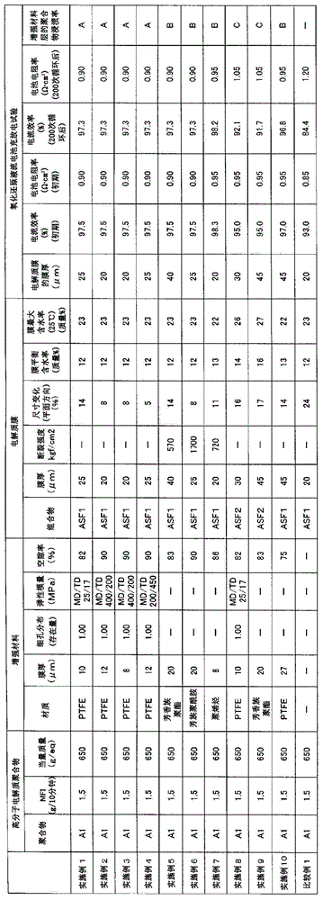
[0453] The equilibrium water content of the obtained electrolyte membrane was 12% by mass, and the maximum water content of the electrolyte membrane when it was immersed in water at 25° C. for 3 hours was 23% by mass.

[0454] The dimensional change in the planar direction was measured using the obtained electrolyte membrane, and the resu...


PUM

PropertyMeasurementUnit
current efficiencyaaaaaaaaaa
boiling pointaaaaaaaaaa

Abstract

This redox flow secondary battery has an electrolyte tank (6) containing: a positive electrode cell chamber (2) containing a positive electrode (1) comprising a carbon electrode; a negative electrode cell chamber (4) containing a negative electrode (3) comprising a carbon electrode; and an electrolyte membrane (5) as a barrier membrane that separates / isolates the positive electrode cell chamber (2) and the negative electrode cell chamber (4). The positive electrode cell chamber (2) contains a positive electrode electrolyte containing an active substance, the negative electrode cell chamber (4) contains a negative electrode electrolyte containing an active substance, and the redox flow secondary battery charges and discharges on the basis of the change in valency of the active substances in the electrolytes. The electrolyte membrane (5) contains an ion exchange resin composition that is primarily a polyelectrolye polymer, and the electrolyte membrane (5) has a reinforcing material comprising a fluorine-based porous membrane.

Description

technical field [0001] The invention relates to a redox flow secondary battery and an electrolyte membrane for the redox flow secondary battery. Background technique [0002] A so-called redox flow secondary battery is a battery that stores and releases electric power, and is a large stationary battery used for equalizing power consumption. [0003] In the redox flow secondary battery, the positive electrode and the electrolyte solution containing the positive electrode active material (positive electrode unit) are separated from the negative electrode and the negative electrode electrolyte solution containing the negative electrode active material (negative electrode unit) with a diaphragm, and the oxidation-reduction reaction of the two active materials is used to Charge and discharge are carried out, the electrolyte solution containing the two active substances is circulated from the storage tank to the electrolytic cell, and the current is taken out for use. [0004] As...

Claims


Application Information

Patent Timeline
Patent Type & Authority Applications(China)
IPC IPC(8): H01M8/18C08J5/22C08L27/18C08L79/04H01B1/06H01M8/02H01M8/10
CPCH01M8/188H01M8/0291C08L27/18H01M2300/0082H01M8/20H01M8/1023Y02E60/521Y02E60/528C08J5/22H01M8/10H01M8/02H01B1/122H01M8/18C08J5/2287C08J2327/18C08L71/12C08L81/04H01M8/0239H01M8/0241H01M8/0289H01M8/0293H01M8/1039H01M8/1058Y02E60/50C08L79/04H01B1/06
Inventor 加藤明宏三宅直人
Owner ASAHI KASEI KK
Why Eureka
Try Eureka