
Electrodialysis device and electrodialysis method using the same

An electrodialysis and electronegative technology, applied in electrodialysis, separation methods, general water supply saving, etc., can solve problems affecting electrode stability, narrow overpotential, surface passivation, etc.

Inactive Publication Date: 2014-09-17
RITEDIA CORPORATION
View PDF7 Cites 1 Cited by
  • Summary
  • Abstract
  • Description
  • Claims
  • Application Information

AI Technical Summary

Problems solved by technology

[0003] Although known metal electrodes (such as: platinum or gold) have good chemical resistance and are not easily corroded by solvents, they can be used in electrodialysis treatment. However, due to their easy hydrophilicity and narrow overpotential, under relatively low voltage, That is, it reacts with water to reduce water to hydrogen or oxidize it to oxygen, so the metal electrode cannot be used under high voltage, so the efficiency of electrodialysis cannot be improved
In recent years, although various electrode materials have attempted to improve this shortcoming, these electrodes are prone to irreversible reactions with oxygen or chemical substances remaining in the solution, and lead to passivation of the surface, thereby affecting the stability of the electrode.

Method used


Image

  • Electrodialysis device and electrodialysis method using the same
  • Electrodialysis device and electrodialysis method using the same
  • Electrodialysis device and electrodialysis method using the same

Examples


Embodiment 1

[0059] This embodiment 1 is roughly similar to the electrodialysis device used in the above-mentioned test example 6, and the only difference is that the working tank capacity of the electrodialysis device in the present embodiment 1 is 4 times the working tank capacity of the electrodialysis device in the above-mentioned test example 6 , and the electrodialysis treatment is carried out in a half-batch manner. Therefore, the present embodiment 1 uses the 10×10cm 2 The electrode is used as the cathode and anode of the electrodialysis device, and the electrodialysis treatment is performed in a half-batch manner, thereby increasing its production capacity. Accordingly, a larger amount of saline solution can be processed in the same time.

Embodiment 2

[0061] This embodiment 2 is roughly similar to the electrodialysis device used in embodiment 1, the only difference is that the working tank capacity of the electrodialysis device in this embodiment 2 is 10000 times the working tank capacity of the electrodialysis device in embodiment 1, and Embodiment 2 adopts the mode of continuous flow to carry out electrodialysis treatment. Therefore, this Example 2 uses the 10×10m prepared in Preparation Example 3 2 The electrodes are used as the cathode and anode of the electrodialysis device, and the electrodialysis treatment is performed in a continuous flow mode, thereby increasing its production capacity. Accordingly, Example 2 can process a larger amount of saline solution in the same time.

[0062] Since the electrodes prepared in the above preparatory examples 2 and 3 all have diamond-like carbon containing 30 atomic percent nitrogen dopant, they are suitable for electrodialysis treatment at a higher voltage, and are more helpful...


PUM

PropertyMeasurementUnit
Thicknessaaaaaaaaaa

Abstract

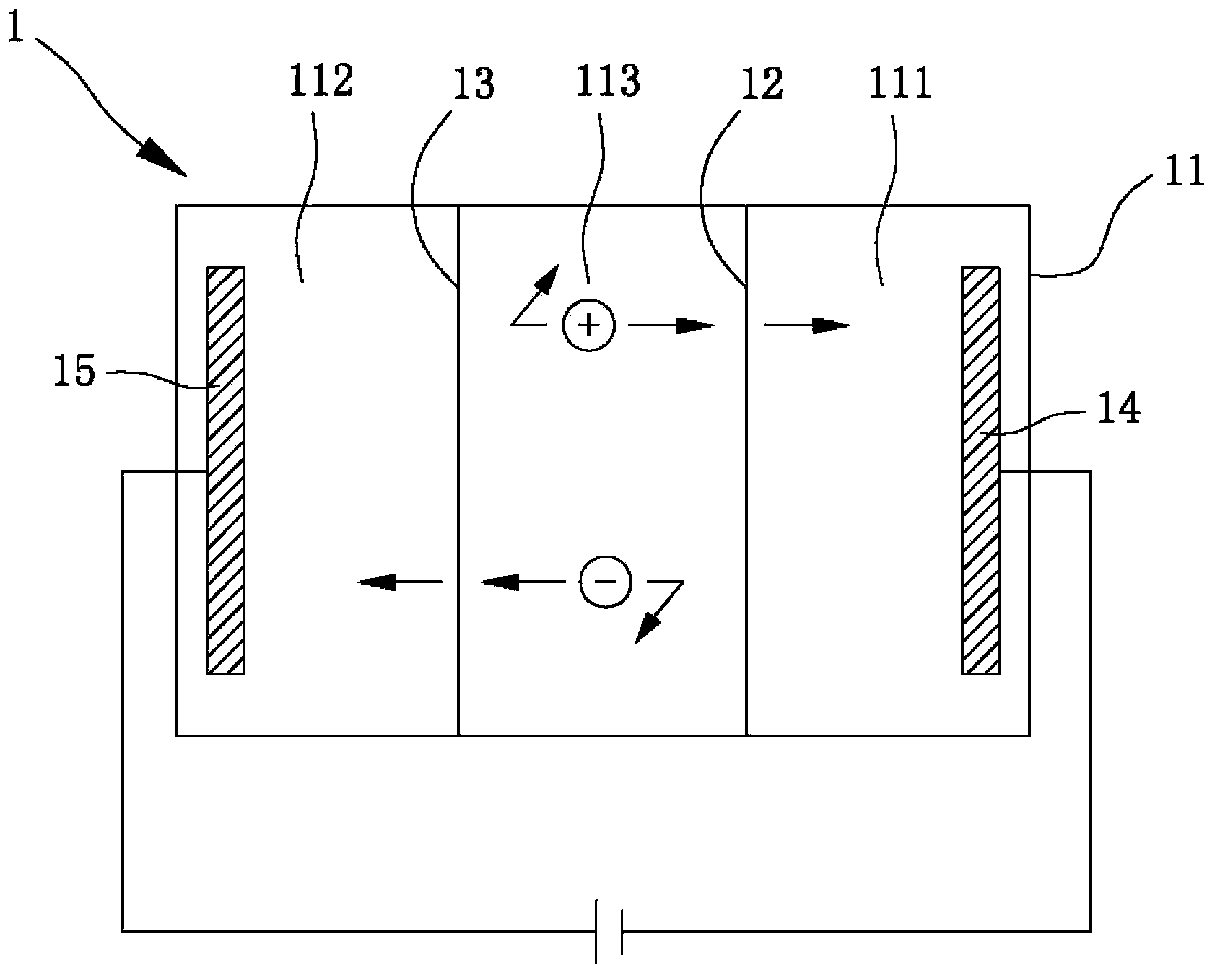
An electrodialysis device comprises a work tank, which comprises a negative electrode chamber, a positive electrode chamber, and a desalination chamber; wherein the negative electrode chamber and the desalination chamber are divided by a positive ion exchange membrane; the positive electrode chamber and the desalination chamber are divided by a negative ion exchange membrane; a negative electrode is arranged in the negative electrode chamber and is communicated until the negative electrode has the electronegativity; a positive electrode is arranged in the positive electrode chamber and is communicated until the positive electrode has the electropositivity; the negative electrode and the positive electrode both have a conductive carbon layer and a substrate, and each conductive carbon layer is composed of conductive twisted non-crystal carbon. The invention also provides a electrodialysis method using the electrodialysis device mentioned above.

Description

technical field [0001] The present invention relates to an electrodialysis device and an electrodialysis method using it, in particular to an electrodialysis device with conductive twisted amorphous carbon electrodes and an electrodialysis method using it Background technique [0002] Due to climate change, rapid population expansion, and industrial development, the global need for fresh water is increasing day by day. Although more than 70% of the earth's surface is covered by water, only about 3.5% of it is fresh water that can be used by human beings. The technology of seawater desalination is an urgent research topic for the world. Known seawater desalination technologies can be mainly divided into evaporation method and membrane method, among which evaporation method can be subdivided into vapor compression method, multi-effect evaporation method, and multi-stage flashing method; while membrane method includes reverse osmosis method and electrodialysis method . The pr...

Claims


Application Information

Patent Timeline
IPC IPC(8): B01D61/48C02F1/469
CPCY02A20/124
Inventor 郑良谦陈玠玮洪太峰林弘正林逸樵刘如熹宋健民
Owner RITEDIA CORPORATION
Learn More