Shaft kiln capable of heating material through dividing wall

A material and shaft kiln technology, which is applied in the vertical kiln and industrial shaft kiln field where the material is heated by the partition wall, can solve the problems of unfavorable carbon dioxide recovery and utilization, and achieve the effects of improving comprehensive economic benefits, reducing exhaust gas emissions, and improving quality.

Active Publication Date: 2014-09-24
SHIJIAZHUANG XINHUA IND FURNACE CO LTD
View PDF6 Cites 11 Cited by
  • Summary
  • Abstract
  • Description
  • Claims
  • Application Information

AI Technical Summary

Problems solved by technology

The carbon dioxide produced by the decomposition of limestone is a valuable resource. Since the decomposed carbo...

Method used


Image

  • Shaft kiln capable of heating material through dividing wall
  • Shaft kiln capable of heating material through dividing wall
  • Shaft kiln capable of heating material through dividing wall

Examples


Embodiment 1

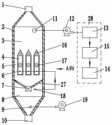
[0018] The shaft kiln of the present invention for heating materials with partition walls, such as figure 1 , figure 2 As shown, it includes waste heat boiler 24, power generation device, carbon dioxide treatment unit 28, kiln body 2, induced draft fan 12, cooling fan 19, feeding equipment, air supply system and fuel supply system. The kiln body is provided with a material inlet 1, a material outlet 10, a decomposition gas outlet 11, a cooling air inlet 9 and a cooling air outlet 18, and the kiln body is divided into a preheating zone 3, a heating zone 5 and a cooling zone 8. The power generation device includes a steam turbine and a generator set, and the steam turbine and the generator set are coaxially connected. The decomposition gas outlet is connected to the carbon dioxide processing unit 28 through the induced draft fan 12, and the cooling fan is connected to the cooling air inlet. The heating zone is provided with three combustion chambers 4, and the upper part of t...

Embodiment 2

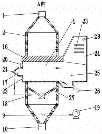
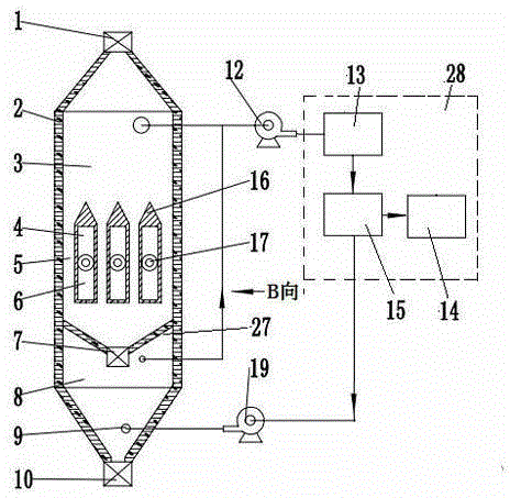
[0021] Another embodiment of the present invention is as image 3 , Figure 4 As shown, the primary air inlet 20 is connected to the oxygen pipeline, pure oxygen is selected as the combustion air, and the secondary air inlet is closed. The decomposed gas outlet is connected to the carbon dioxide processing unit 28 through the induced draft fan 12, and the exhaust port 29 of the waste heat boiler is also connected to the carbon dioxide processing unit. The carbon dioxide and pure oxygen produced by limestone decomposition and the carbon dioxide produced by fuel combustion enter the carbon dioxide processing unit together. The carbon dioxide processing unit includes a carbon dioxide purification device 13 , a carbon dioxide storage tank 15 and a carbon dioxide supercritical power generation device 14 . The carbon dioxide purification device 13 is equipped with dehydration equipment, desulfurization equipment and cooling equipment. The carbon dioxide purification device is conn...


PUM


Abstract

The invention relates to a shaft kiln capable of heating a material through a dividing wall. The shaft kiln comprises a waste heat boiler, a generating set, a kiln body, a draught fan, a cooling fan, feeding equipment, an air supply system and a fuel supply system, wherein the kiln body is provided with a feeding hole, a discharging hole, a decomposed air outlet, a cooling air inlet and a cooling air outlet; a combustion chamber is arranged in a heating zone; a combustor is arranged at one end of the combustion chamber and the other end of the combustion chamber is communicated with the waste heat boiler; a baffle is arranged between the heating zone and a cooling zone; the baffle is of a conical platform structure; a material lock is arranged at the lower part of the conical platform; a steam pipe coil is arranged on the waste heat boiler and connected to the generating set; the decomposed air outlet is connected with a carbon dioxide treatment unit through the draught fan; the cooling air outlet is connected to a secondary air inlet or the inlet of the draught fan; and the inlet of the cooling fan is connected with the carbon dioxide treatment unit or communicated with the air. By heating the material inside the kiln body in a flame isolation manner through use of heat conducting brick masonries, improvement of the quality of a roasted material can be facilitated, high-purity carbon dioxide can be recycled and energy consumption of a lime kiln can be reduced.

Description

technical field [0001] The invention belongs to the technical field of industrial furnaces and kilns, and relates to an industrial shaft kiln, in particular to a shaft kiln with partition walls for heating materials. Background technique [0002] Lime kiln waste heat recovery and utilization can save energy consumption, reduce lime production costs, and reduce pollutant emissions at the same time. Lime kiln is a large-scale high-energy-consuming device. With the rapid development of the national economy, the waste heat of industrial furnaces is very rich and has great potential for utilization. The iron and steel industry, calcium carbide industry, alumina industry and refractory material industry are major lime consumers. The rapid growth of the above industries has driven the rapid development of lime kilns. During the production process of large-scale active lime production line, the flue gas discharge temperature is high, about 240-260°C. Effective use of this part of ...

Claims


Application Information

Patent Timeline
IPC IPC(8): C04B2/12
CPCY02P40/40
Inventor 贾会平
Owner SHIJIAZHUANG XINHUA IND FURNACE CO LTD
Why Eureka
Try Eureka