
Waveguide-type W wave band circularly polarized horn antenna

A horn antenna and waveguide technology, applied in waveguide horns, circuits, etc., can solve the problems of increased processing difficulty, small gain, and difficult implementation, and achieve the effects of increasing antenna gain, increasing radiation surface, and simplifying the structure

Active Publication Date: 2014-09-24
NANJING UNIV OF SCI & TECH
View PDF3 Cites 16 Cited by
  • Summary
  • Abstract
  • Description
  • Claims
  • Application Information

AI Technical Summary

Problems solved by technology

[0002] After the 1950s, with the development of satellite communication, remote sensing and telemetry technology, the expansion of the application range of radar, and the need for tracking and measurement of high-speed targets under various polarization modes and climatic conditions, it has been difficult for a single polarization mode to meet the electrical equipment requirements
For example, for a helical antenna, the higher the frequency, the shorter the wavelength, and the corresponding smaller size of the helical antenna. At the same time, the coupling effect between the coils is intensified, which seriously affects the performance of the antenna; Due to some shortcomings of its own, such as narrow frequency band, low gain, complex high-performance antenna feed network, difficult to achieve ideal polarization, and generally a certain degree of distortion, etc., these problems have a greater impact when the frequency is higher and some other existing waveguide-type circularly polarized antennas are difficult to apply in the W-band due to the reduced size and increased processing difficulty.

Method used


Image

  • Waveguide-type W wave band circularly polarized horn antenna
  • Waveguide-type W wave band circularly polarized horn antenna
  • Waveguide-type W wave band circularly polarized horn antenna

Examples


Embodiment Construction

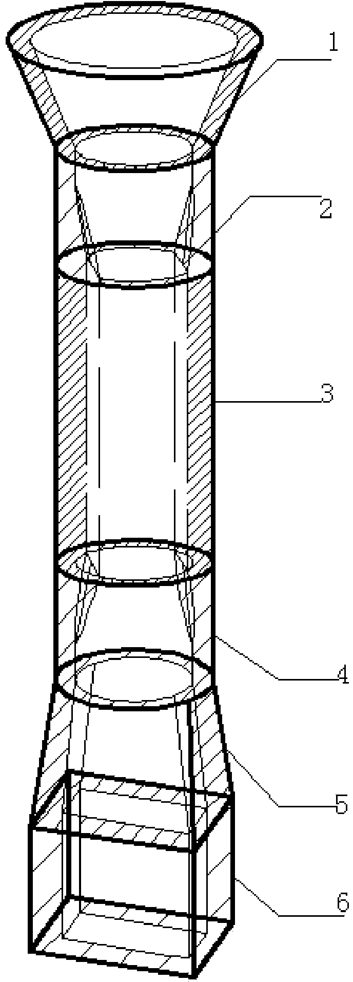
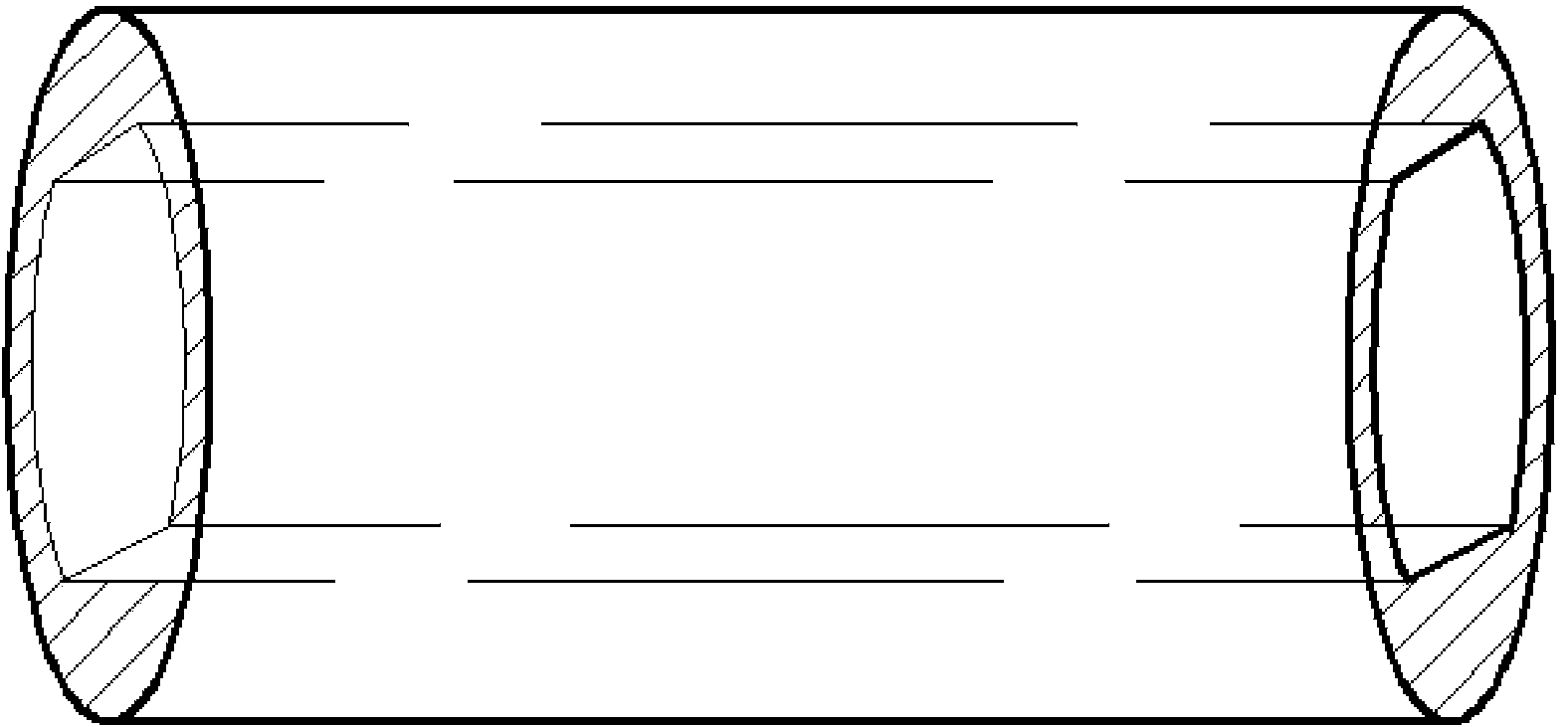
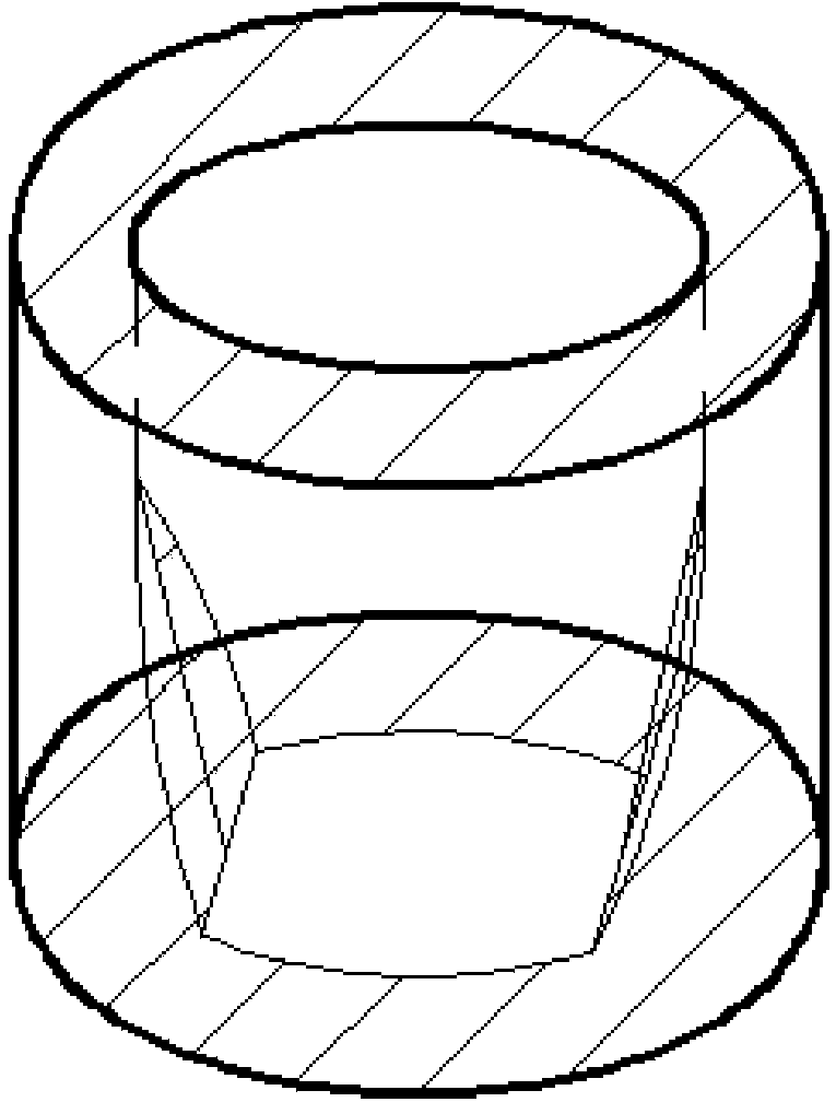
[0020] In conjunction with the accompanying drawings, a waveguide-type W-band circularly polarized horn antenna of the present invention includes a circular waveguide radiator 1, an output impedance matching waveguide 2, a circular waveguide polarizer 3, an input impedance matching waveguide 4, and a rectangular waveguide connected in sequence. The circular transition waveguide 5 and the rectangular waveguide 6, the above-mentioned components are coaxially arranged and the inner cavity transitions smoothly; wherein the circular waveguide inner cavity of the circular waveguide polarizer 3 includes two mutually parallel planes, and the planes are connected to the circular waveguide polarizer. Parallel to the central axis of the waveguide, the inner cavity plane is also at a 45° angle to the inner cavity plane of the rectangular waveguide 6; the output impedance matching waveguide 2 and the input impedance matching waveguide 4 have the same structure and are symmetrically arranged ...


PUM


Abstract

The present invention relates to a waveguide-type W wave band circularly polarized horn antenna which is mainly used in the fields, such as millimeter wave communication, millimeter wave detection, remote sensing, remote measurement, etc. The waveguide-type W wave band circularly polarized horn antenna comprises a circular waveguide radiator, an output impedance matching waveguide, a circular waveguide polarizer, an input impedance matching waveguide, a rectangular- circular transition waveguide and a rectangular waveguide which are connected orderly. According to the present invention, by designing the circular waveguide polarizer, the circular polarization characteristic of an electromagnetic wave is realize; by designing the output impedance matching waveguide and the input impedance matching waveguide, the good impedance matching is realized, and the standing-wave ratio of the antenna is reduced; by designing a horn radiation structure, the antenna gain is improved.

Description

technical field [0001] The invention relates to a horn antenna, in particular to a waveguide-type W-band circularly polarized horn antenna. Background technique [0002] After the 1950s, with the development of satellite communication, remote sensing and telemetry technology, the expansion of the application range of radar, and the need for tracking and measurement of high-speed targets under various polarization modes and climatic conditions, it has been difficult for a single polarization mode to meet the electrical equipment requirements. These new applications put forward a series of new issues for the antenna, requiring the antenna to have high gain, high resolution, wide frequency band and circular polarization. With the in-depth research on circularly polarized antennas, circularly polarized antennas can resist cloud and rain interference, can interfere with and detect various linearly polarized and elliptically polarized waves of the enemy, and can eliminate the int...

Claims


Application Information

Patent Timeline
Patent Type & Authority Applications(China)
IPC IPC(8): H01Q13/02
Inventor 彭树生许建中范娇娇吴礼肖泽龙
Owner NANJING UNIV OF SCI & TECH
Learn More