
Reformed coal production equipment, and method for controlling same

A manufacturing equipment and modification technology, applied in the field of modified coal manufacturing equipment and its control, can solve the problems of additional energy, increased production cost of modified coal, inability to efficiently remove tar, etc., and achieve the effect of efficient maintenance

Inactive Publication Date: 2014-09-24
MITSUBISHI HEAVY IND LTD
View PDF8 Cites 3 Cited by
  • Summary
  • Abstract
  • Description
  • Claims
  • Application Information

AI Technical Summary

Problems solved by technology

[0011] However, if the decoking method described in the above-mentioned Patent Document 1 is applied to the above-mentioned upgraded coal production facility, although the oxygen concentration-adjusted gas whose oxygen concentration is adjusted is directly supplied to the carbonization device, it is possible to stop However, if an attempt is made to produce the oxygen concentration-adjusting gas from air or an inert gas (nitrogen or water vapor), a device for this purpose is required, which will cause Increased production cost of modified coal due to this device
In addition, in order to react with the tar, the temperature of the oxygen concentration-adjusting gas must be raised in advance, and additional energy is required.
In other words, tar cannot be removed efficiently
[0012] Since in the thermal decomposition method of the processed product by means of an external heating furnace described in the above-mentioned Patent Document 2, the carbide of the organic matter of the processed product generated due to thermal decomposition burns itself, if this method is applied to the modification In a coal production facility, even when the facility is stopped, it is necessary to supply coal to the carbonization device and to burn the coal itself, resulting in a decrease in the production amount of modified coal.

Method used

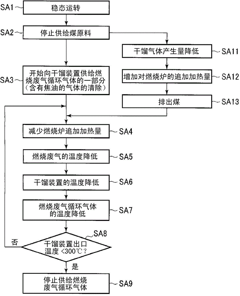

Image

  • Reformed coal production equipment, and method for controlling same
  • Reformed coal production equipment, and method for controlling same
  • Reformed coal production equipment, and method for controlling same

Examples


Embodiment 2

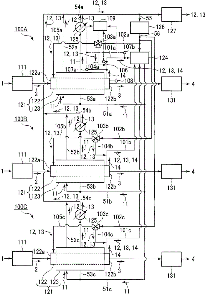
[0054] based on image 3 , Figure 4 A. and Figure 4 B The upgraded coal production facility of the second embodiment of the present invention will be described.

[0055] The modified coal manufacturing equipment of this embodiment is as image 3 As shown, three upgraded coal production facility main bodies 100A, 100B, and 100C arranged in parallel are provided. The upgraded coal manufacturing facility main bodies 100A, 100B, and 100C are the same as the upgraded coal manufacturing facility 100 of the first embodiment described above, and include a drying device 111 , a carbonization device 121 , and a cooling device 131 , respectively.

[0056] The upgraded coal manufacturing facility of this embodiment is the same as the upgraded coal manufacturing facility 100 of the above-mentioned first embodiment, and includes one combustion furnace 124 , one blower 126 and one exhaust gas treatment device 127 . The gas discharge port of the blower 126 is connected to the gas receiv...


PUM


Abstract

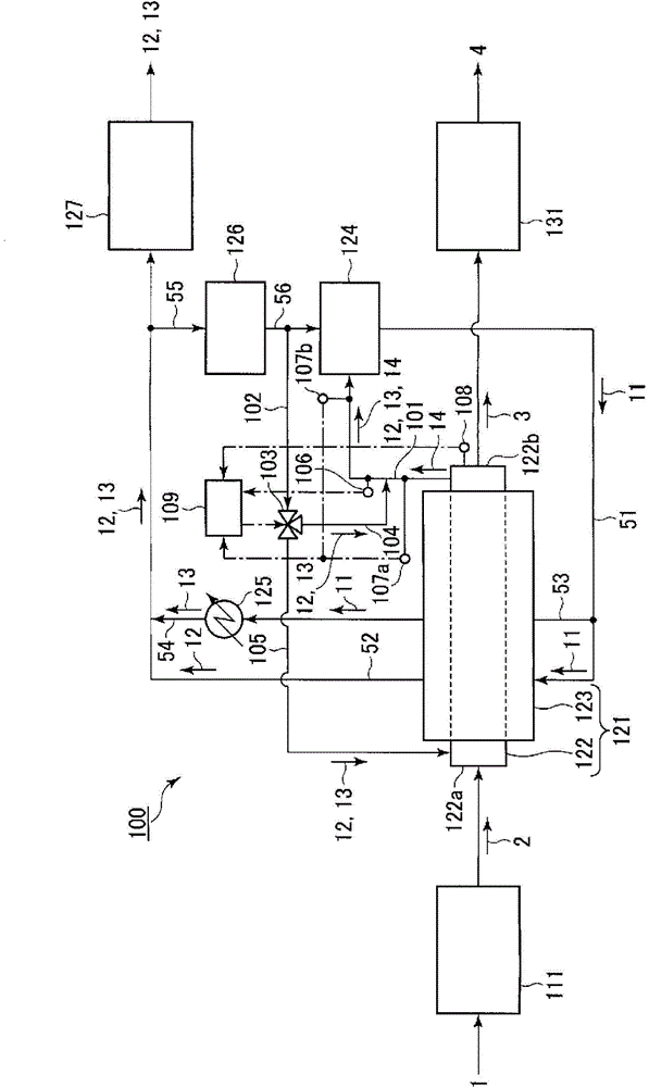
The purpose of the present invention is to provide reformed coal production equipment whereby it is possible to efficiently remove tar without lowering the production amount of reformed coal even when the equipment is stopped. Reformed coal production equipment provided with: a combustion furnace (124) for generating heated gas; a dry distillation gas supply pipe (101) for supplying dry distillation gas (14) that was generated at the inner cylinder (122) of a dry distillation device (121) to the combustion furnace; a vapor generator (125) to which a portion of the heated gas (11) generated at the combustion furnace is supplied and which generates waste heat gas (13) by subjecting the heated gas to heat exchange; and a discharge pipe (52), a waste heat gas delivery pipe (53), a mixed gas delivery pipe (55), a blower (126), a mixed gas supply pipe (56), a mixed gas branching pipe (102), a flow rate adjustment valve (103), and a mixed gas allocation pipe (105) which supply and allocate, to the aforementioned inner cylinder, the waste heat gas and low-temperature heated gas (12) generated by indirectly heating dried coal (2) by means of the heated gas within the outer cylinder (123) of the dry distillation device.

Description

technical field [0001] The present invention relates to modified coal manufacturing equipment and a control method thereof, and is particularly useful when applied to modifying low-grade coal (low-grade coal) such as lignite and sub-bituminous coal, which is porous and has a high moisture content. Background technique [0002] Porous and high-moisture low-grade coal (low-grade coal) such as lignite and sub-bituminous coal has a low calorific value per unit weight, so it is dried by heat treatment to increase the calorific value per unit weight. [0003] As a reformed coal manufacturing facility for reforming such low-grade coal, there is, for example, a device that includes an indirect heating system carbonization device that indirectly heats low-grade coal with heating gas to dry-distill it, and converts the The pyrolysis gas generated in the pyrolysis device is supplied through the pyrolysis gas supply pipe, and the pyrolysis gas and the like are combusted to generate the ...

Claims


Application Information

Patent Timeline
Patent Type & Authority Applications(China)
IPC IPC(8): C10L9/08C10B47/30C10B57/10
CPCC10B49/02C10L9/08Y02E50/30C10L5/04C10B47/30C10B1/10C10B51/00Y02P20/129
Inventor 中川庆一大本节男佐藤文昭佐藤淳
Owner MITSUBISHI HEAVY IND LTD
Learn More