
Tritium-blocking plating and preparation method thereof

A technology for coating and blocking tritium, applied in coatings, layered products, sputtering, etc., can solve the problems of small tritium penetration reduction coefficient and poor tritium blocking effect, and achieve the reduction of tritium permeation channels, excellent performance, and film. Strong base binding effect

Inactive Publication Date: 2014-10-01
SICHUAN INST OF MATERIALS & TECH
View PDF2 Cites 8 Cited by
  • Summary
  • Abstract
  • Description
  • Claims
  • Application Information

AI Technical Summary

Problems solved by technology

[0005] The object of the present invention is to: provide a kind of anti-tritium coating and preparation method thereof for the problem that the tritium penetration reduction factor (PRF) of the currently researched anti-tritium coating is far less than the theoretical value, and the anti-tritium effect is poor

Method used

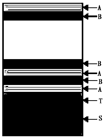
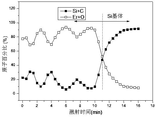
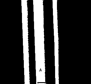

Image

  • Tritium-blocking plating and preparation method thereof
  • Tritium-blocking plating and preparation method thereof
  • Tritium-blocking plating and preparation method thereof

Examples


Embodiment 1

[0045] 1) Substrate surface pretreatment: use glow discharge Ar ions to bombard the substrate surface to clean the substrate surface until the substrate surface is cleaned. Among them, the bias voltage is -500~-1000V, and the vacuum is 1.0~1.5Pa.

[0046] 2) Depositing the Er transition layer: after cleaning the surface of the substrate in step 1, adjust the argon gas to maintain the vacuum at 0.2-0.5Pa, and apply a pulse bias voltage of -800V to -1500V with a duty ratio of 15% on the substrate, Turn on the target sputtering power supply, and deposit an Er film of about 100 nm, namely the Er transition layer.

[0047] 3) Deposition of Er 2 o 3 Coating: adjust the argon gas so that the vacuum pressure is about 0.5Pa, apply a bias voltage of -90V to the Er transition layer of the substrate, turn on the radio frequency power supply, and deposit a layer of Er2O3 coating with a thickness of 50nm.

[0048] 4) Deposit SiC coating: adjust the argon gas so that the vacuum pressure i...

Embodiment 2~6

[0051] The steps of Examples 2 to 6 are basically the same as those of Example 1, the main difference being that during the coating deposition process, the workpiece bias voltage, vacuum pressure, deposition thickness and number of film layers are different, and the specific parameters are shown in Table 1 below.

[0052] The relevant parameter of table 1 embodiment 1-6

[0053]


PUM

PropertyMeasurementUnit
Thicknessaaaaaaaaaa

Abstract

The invention discloses a tritium-blocking plating and a preparation method of the tritium-blocking plating, aiming to solve the problems that tritium penetration reduction factors (PRF) of tritium-blocking platings researched at present are all far less than a theoretical value and the tritium-blocking effect is poor. The tritium-blocking plating comprises a base body, and a multilayer film arranged on the base body, wherein the multilayer film is formed by alternatively depositing Er2O3 platings and SiC platings. According to the tritium-blocking plating, two kinds of platings of Er2O3 and SiC are compounded to form a tritium-blocking plating with a multilayer structure; and hydrogen capturing bonds such as C<->, O<-> and Si<-> are simultaneously introduced by the tritium-blocking plating, thus the tritium-blocking performance of the base body can be effectively improved; meanwhile, an interface is formed between each Er2O3 plating and each SiC plating, thus the probability of perfoliate holes and defects of the tritium-blocking plating is reduced, the compactness of the integral tritium-blocking plating is improved, and the number of tritium penetration channels is reduced; and the interfaces formed between the Er2O3 platings and the SiC platings are capable of effectively improving the tritium-blocking performance of the plating. The tritium-blocking plating provides a new approach for reducing and even blocking tritium penetration for the field of nuclear energy.

Description

technical field [0001] The invention relates to the field of nuclear energy and material engineering, in particular to a tritium blocking coating and a preparation method thereof. Background technique [0002] With the further deepening of the threat of the world energy crisis and the inherent defects of the existing energy system, people are paying more and more attention to the green energy system, and nuclear energy (especially fusion reactors and hybrid reactors fueled by deuterium and tritium) is expected to become an alternative Green energy system for conventional energy. Tritium is radioactive, and tritium penetration will cause great harm to operators, cause radioactive contamination of the environment or devices, and lead to hydrogen embrittlement of structural materials, which also limits the application of nuclear energy using tritium as a raw material to a certain extent. [0003] The anti-tritium coating is to prepare an anti-tritium permeation layer with a lo...

Claims


Application Information

Patent Timeline
IPC IPC(8): B32B9/04C23C14/35C23C14/08C23C14/06C23C14/02
Inventor 朱生发吴艳萍刘天伟唐凯魏强肖红蒋驰饶永初
Owner SICHUAN INST OF MATERIALS & TECH
Learn More