
Resonant optical gyroscope based on high-K fluoride resonant cavity

An optical gyroscope and fluoride technology, applied in Sagnac effect gyroscopes, gyroscopes/steering sensing devices, measuring devices, etc., can solve the problem of affecting the angular velocity measurement of the gyroscope, unable to meet the requirements of the gyroscope navigation level, and the resonant cavity Q problems such as low value, to achieve the effect of simple structure, high Q value, and wide transmission band

Inactive Publication Date: 2014-10-01
ZHONGBEI UNIV
View PDF5 Cites 8 Cited by
  • Summary
  • Abstract
  • Description
  • Claims
  • Application Information

AI Technical Summary

Problems solved by technology

Usually, changes in temperature in the environment or changes in external vibrations will cause a relative change in the peak position of the resonance peak corresponding to the polarization eigenstate, thereby causing a frequency difference caused by polarization fluctuations, which will directly affect the gyro rotation. Measurement of Angular Velocity
[0008] In the traditional resonant cavity selection, most of the resonant cavity materials use silicon dioxide, because SiO 2 It has good insulation properties and a stable silicon dioxide-silicon substrate interface. However, due to the low Q value of the resonator made of silicon dioxide, the size can only be on the order of tens of um, which cannot meet the requirements of gyro navigation.

Method used


Image

  • Resonant optical gyroscope based on high-K fluoride resonant cavity
  • Resonant optical gyroscope based on high-K fluoride resonant cavity
  • Resonant optical gyroscope based on high-K fluoride resonant cavity

Examples


Embodiment Construction

[0030] The present invention will be further described below in conjunction with accompanying drawing:

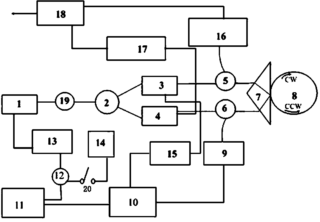
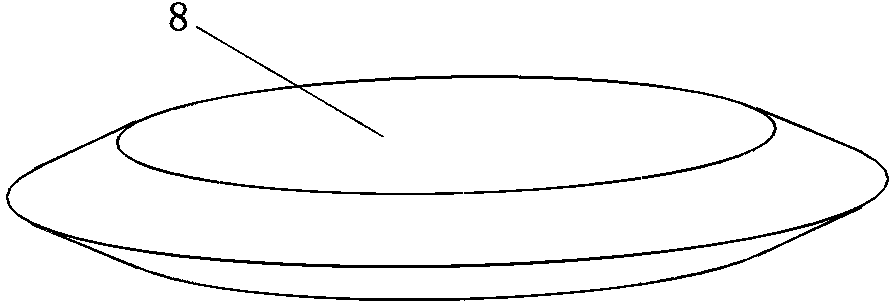
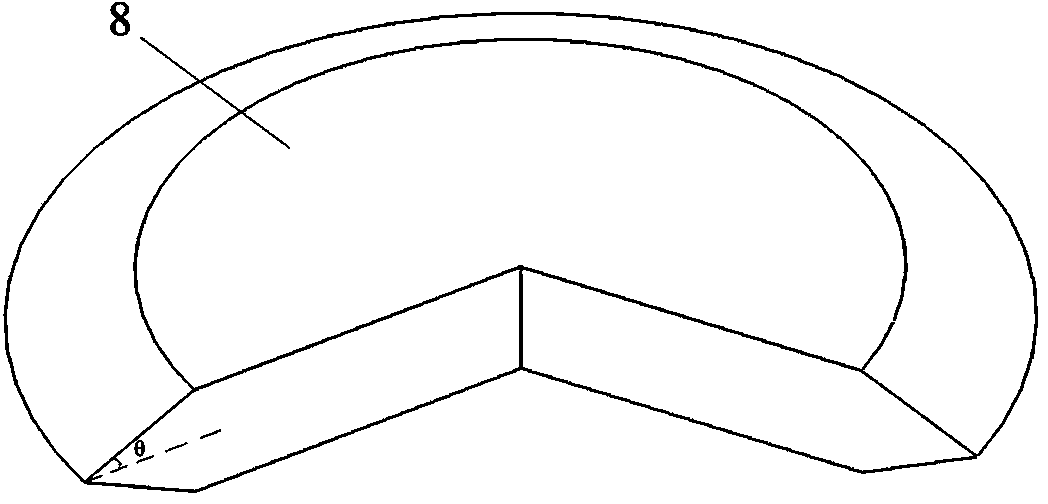
[0031] Such as Figure 1 to Figure 5 As shown, a resonant optical gyro based on a high-K fluoride resonator cavity, including a laser 1, a beam splitter 2, an A phase modulator 3, a B phase modulator 4, and an A ring resonator 5 integrated on a silicon substrate , B ring resonator 6, triangular prism 7, fluoride wedge cavity 8, A detector 9, A lock-in amplifier 10, PI circuit 11, adder 12, high voltage amplifier 13, C signal generator 14, A signal generator 15, B detector 16, B signal generator 17, B lock-in amplifier 18, isolator 19; A signal generator 15, B signal generator 17, C signal generator 14 have the same structure; A phase modulator 3, The B phase modulator 4 has the same structure; the A detector 9 and the B detector 16 have the same structure; the fluoride wedge-shaped cavity 8 refers to a disc made of fluoride crystal with a precision of 0.9999 or more, and t...


PUM


Abstract

The invention discloses a resonant optical gyroscope based on a high-K fluoride resonant cavity. The resonant optical gyroscope comprises a laser, a beam splitter, phase modulators, ring-shaped resonators, a triangular prism, a fluoride wedge-shaped cavity, detectors, lock-in amplifiers, a PI circuit, an adder, a high-voltage amplifier, signal generators and an isolator; the PI circuit is used for modulating optical signals to enable physical quantities extracted from signals output from the detector A and B to be capable of reacting the rotation angle of a carrier, and the frequency of the emergent light of a light source and a modulating voltage of the phase modulators can be respectively changed according to the physical quantities, the feedback of an optical path can be realized, and the purpose that the optical paths propagating in the fluoride wedge-shaped cavity clockwise and anti-clockwise are resonant can be realized.

Description

technical field [0001] The invention belongs to the technical field of gyroscopes, and relates to an angular rate measuring device, specifically a method of light transmission in a closed optical path based on the Sagnac effect, which uses a fluoride wedge-shaped cavity and is realized by multi-beam interference A resonant optical gyroscope for measuring angular velocity, specifically a resonant optical gyroscope based on a high-K fluoride resonant cavity. Background technique [0002] As the core component of the inertial navigation system, the gyro-inertial device is used in land, sea, air and space guidance, navigation and control technology fields such as land, sea, air and space guidance, navigation and control technology, as well as satellite attitude Control, camera stabilization, image stabilization, geodetic surveying, resource surveying, robotics, consumer electronics and other industries have a wide range of application backgrounds, and their development is of gre...

Claims


Application Information

Patent Timeline
Patent Type & Authority Applications(China)
IPC IPC(8): G01C19/66
CPCG01C19/727
Inventor 薛晨阳张文栋刘耀英刘俊闫树斌唐军安盼龙张志东郑华
Owner ZHONGBEI UNIV
Learn More