
Drive control system and phase shift amount control method of a ferrite phase shifter

A technology of drive control and phase shifter, which is applied to the automatic control of power and electrical components, etc. It can solve the problem that the drive control circuit cannot realize the phase shift control, the phase shift amount of the phase shifter cannot be accurately controlled, and the synthetic beam of the radar There are problems such as blind areas, to achieve the effect of reducing beam scanning blind areas, reducing saturation magnetization, and overcoming the effects

Inactive Publication Date: 2017-05-10
UNIV OF ELECTRONICS SCI & TECH OF CHINA
View PDF3 Cites 0 Cited by
  • Summary
  • Abstract
  • Description
  • Claims
  • Application Information

AI Technical Summary

Problems solved by technology

The Chinese patent "Ferrite Phase Shifter Digital Control Circuit" with application number 201120424366.3 proposes a control circuit based on MCU, reset pulse signal, set pulse generator and drive circuit, but the circuit structure requires an external clock to realize Pulse width adjustment, and the phase shift amount of the phase shifter cannot be precisely controlled
The Chinese patent "Precise Digital Controlled Frequency Phase Shifter" with application number 200820222701.X proposes a structure including a single-chip microcomputer system, but this structure has a small driving current and a low application frequency range, so it cannot be applied to a ferrite phase shifter , but also requires an external reference source for the function of the circuit
The performance of ferrite devices has a great correlation with the ambient temperature. In some special applications (such as phased array radar), the ferrite phase shifter adopts the drive control circuit of the above two structures and cannot achieve accurate phase shift control. It will cause the synthetic beam of the radar to have a blind spot in the space

Method used


Image

  • Drive control system and phase shift amount control method of a ferrite phase shifter
  • Drive control system and phase shift amount control method of a ferrite phase shifter
  • Drive control system and phase shift amount control method of a ferrite phase shifter

Examples


Embodiment Construction

[0031] A specific embodiment of the present invention will be described in detail below.

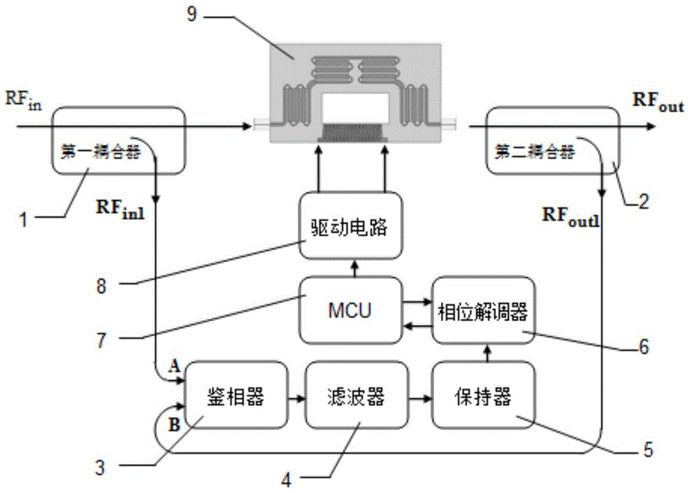
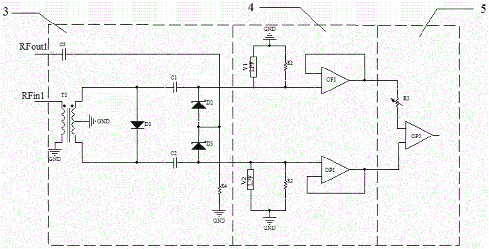
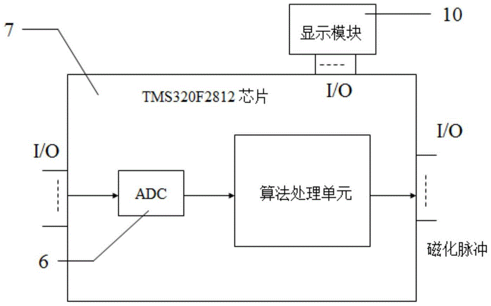
[0032] Embodiment is the drive control system of the ferrite phase shifter working in X band, figure 1 Schematic diagram of the drive control system. Wherein, the first coupler 1 adopts a circuit structure with a coupling degree of 10 dB, and the second coupler 2 adopts a circuit structure with a coupling degree of 6 dB. The circuit schematic diagram of phase detector 3, low-pass filter 4 and holder 5 is as follows figure 2 shown. The phase detector 3 adopts an analog sampling phase detector structure, and is composed of a balun T1, a fast recovery diode D3, sampling switching capacitors C1 and C2, Schottky diodes D1 and D2, a DC blocking capacitor C5, and a matching resistor R4. Filter 4 adopts an RC low-pass structure and an operational amplifier inverter in series, and is composed of low-pass RC filters V1 and V2, charge discharge resistors R1 and R2, and voltage followers OP1 an...


PUM


Abstract

The invention provides a drive control system of a ferrite phase shifter and a control method of a phase shift amount, belonging to the field of measurement and control of microwave devices. The drive control system includes a first coupler, a second coupler, a phase detector, a filter, a keeper, a phase demodulator, an MCU, a drive circuit, and a ferrite phase shifter. The first and second couplers will The microwave signal with a power of 2-10dBm is coupled and separated, output to the phase detector, the phase detector detects the phase of the microwave signal, and outputs it to the filter, the filter selects the required phase difference signal, and outputs it to the holder, the holder Amplify or attenuate the reserved signal, output to the phase demodulator, the phase demodulator performs phase demodulation on the signal, and output to the MCU, the MCU judges and analyzes the demodulated signal, and controls the driving circuit. The drive control system of the invention overcomes the influence of temperature on the ferrite phase shifter and the non-ideal problems of the magnetization pulse signal, and realizes precise control of the phase shift amount.

Description

technical field [0001] The invention belongs to the field of measurement and control of microwave devices, and in particular relates to a drive control system of a ferrite phase shifter and a method for controlling the phase shift amount of the ferrite phase shifter. Background technique [0002] The ferrite phase shifter is mainly used in the field of microwave communication, and its function is mainly to change the phase of the microwave signal. It is widely used in phased array radar due to its advantages such as high phase shift figure of merit, strong anti-radiation ability, and ultra-wideband. The ferrite phase shifter is a lock-type device that works in the remanence state. It mainly realizes the phase change of the microwave signal through the change of the remanence state, and the change of the remanence state requires a special magnetization device to realize . In the early rotating field ferrite phase shifter, the change of the magnetization state was mainly real...

Claims


Application Information

Patent Timeline
Patent Type & Authority Patents(China)
IPC IPC(8): H03L7/06
Inventor 杨青慧王明许玥张怀武贾利军廖宇龙文岐业
Owner UNIV OF ELECTRONICS SCI & TECH OF CHINA
Learn More