
Method and device for producing synthetic gas and method and device for synthesizing liquid fuel

A technology for synthesizing gas and liquid fuels, which is applied in the production of hydrogen/synthesis gas, biofuel, pyroligneous acid, etc., to achieve the effect of easy collection/transportation and simple treatment

Inactive Publication Date: 2014-11-19
NAGASAKI INSTITUTE OF APPLIED SCIENCE +2
View PDF3 Cites 2 Cited by
  • Summary
  • Abstract
  • Description
  • Claims
  • Application Information

AI Technical Summary

Problems solved by technology

[0006] On the other hand, there are also researches on improving bio-liquid fuels and commercializing them as general liquid fuels, but the status quo is limited to low-quality fuels alongside low-quality heavy oils

Method used


Image

  • Method and device for producing synthetic gas and method and device for synthesizing liquid fuel
  • Method and device for producing synthetic gas and method and device for synthesizing liquid fuel
  • Method and device for producing synthetic gas and method and device for synthesizing liquid fuel

Examples


Embodiment 1

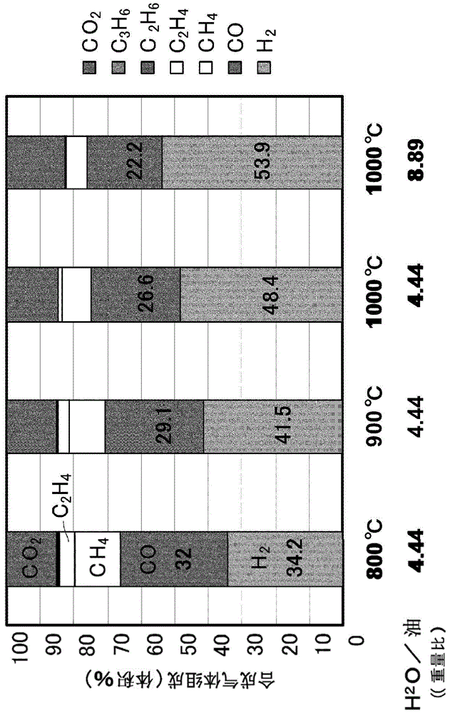
[0047] As a test device, a flow-through reactor in which reaction tubes made of SUS with an inner diameter of 54 mm and a length of 900 mm were installed vertically and electrically heated uniformly from the outer periphery was used. The above-mentioned space in the reaction tube with an inner diameter of 54 mm and a length of 900 mm is a gasification space. On the upstream side (below the gasification space), an electric furnace heating steam generating device is installed, and steam is supplied from the bottom of the reaction tube. The sample was fed through an insertion tube with an inner diameter of 5 mm using a microdoser in an upward flow of water vapor. A filter for collecting soot in the synthesis gas released from the reaction tube, a condenser for cooling the generated gas, and a drain bin are installed on the downstream side (above the gasification space) after the reaction.

[0048] The vaporization space is heated up to a specified temperature, and nitrogen and a...

Embodiment 2

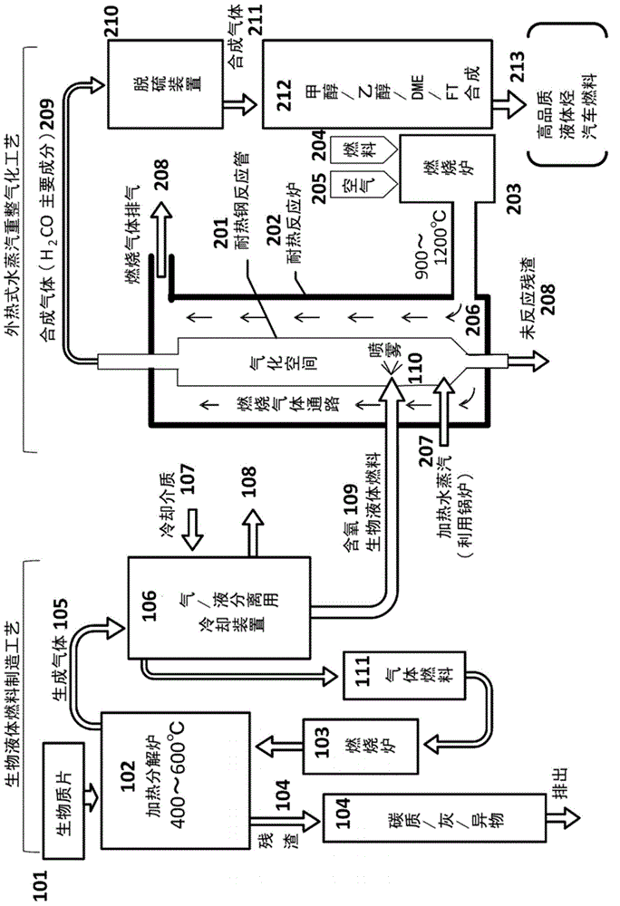
[0070] figure 2 It is an explanatory drawing which shows the manufacturing method and manufacturing apparatus of the synthetic gas of the example based on this invention.

[0071] In the figure, biomass chips 101 are heated to 400-600° C. in a thermal decomposition furnace 102 with hot gas from a combustion furnace 103, and the solid residue (carbonaceous / ash / foreign matter) 104 generated at this time is removed from the combustion furnace. Bottom discharge. The generated gas 105 taken from the upper part of the pyrolysis furnace 102 is separated into gaseous fuel 111 and biological liquid fuel 109 in the gas / liquid separation and cooling device 106. 107 and 108 are the inlet and outlet of the cooling medium, respectively.

[0072] In this state, bio-liquid fuel 109 is generally an oxygen-containing hydrocarbon structure. The bioliquid fuel is directed into a refractory reactor furnace 202 . In the steam reforming gasification process of the present invention, the oxygen-c...


PUM


Abstract

Provided is a method for producing synthetic gas with which a virtually soot-free synthetic gas having a good composition can be efficiently obtained by a simple device using a liquid biofuel as the starting material, and it is thereby possible to produce a high-quality liquid fuel such as methanol, gasoline or kerosene. Steam and a liquid biofuel produced by pyrolysis of a biomass are fed to the gasification space inside a reactor tube that is not loaded with a catalyst inside the reactor tube and heated to 800 to 1,200ºC from the outside via the reactor tube walls to induce an endothermic reaction and thereby a steam reforming chemical reaction between the steam and the liquid biofuel. By setting the molar ratio of the fed steam and carbon in the liquid biofuel ([H2O] / [C]) at 0.3 or higher, a synthetic gas having a good composition that is virtually free of tar and soot and is primarily H2 and CO is obtained.

Description

technical field [0001] The present invention relates to effective utilization of biomass, and specifically relates to a method for producing synthesis gas, which is a high-quality and clean chemical raw material, from biomass. Furthermore, it relates to a technology that can industrially produce synthesis gas having a high ratio of hydrogen H 2 and carbon monoxide CO, which are chemical raw materials that cannot be obtained from conventional biomass. Background technique [0002] Biomass is usually solid, so it lacks convenience in combustibility, collection, transportation, etc., and economical efficiency becomes a problem. Therefore, liquid fuel (also referred to as bio-oil; hereinafter, described as bio-liquid fuel) produced from biomass is expected as a practical fuel. [0003] Bio-liquid fuel is a liquid fuel that converts solid biomass such as grass and wood as a raw material through heat treatment (rapid pyrolysis, etc.) into a liquid fuel that is easy to handle. Sp...

Claims


Application Information

Patent Timeline
IPC IPC(8): C01B3/22C10J3/00
CPCC10B49/02C10B53/02C01B2203/1211C01B2203/0216C10G2/32Y02E50/32C10C5/00C10G2300/1011C01B2203/1258C01B3/32C10G2/30Y02P30/20C01B2203/0805Y02E50/10Y02E50/30C01B3/323C07C1/041C07C1/0485C07C29/1518
Inventor 坂井正康村上信明森光信孝武井泰典长谷川昭
Owner NAGASAKI INSTITUTE OF APPLIED SCIENCE
Learn More