Device and method for separating and purifying mixed gas of sulfur hexafluoride and nitrogen

A mixed gas and purification technology, applied in separation methods, chemical instruments and methods, sulfur and halogen compounds, etc., can solve the problems that the gas cannot be recycled and the mixed gas cannot be separated, and achieves strong practicability and device structure. The effect of reasonable and widespread promotion of value

Active Publication Date: 2014-12-03
STATE GRID CORP OF CHINA +2
View PDF7 Cites 12 Cited by
  • Summary
  • Abstract
  • Description
  • Claims
  • Application Information

AI Technical Summary

Problems solved by technology

[0004] The present invention is to solve the existing SF in the prior art 6 and N 2 The mixed gas cannot be separated, resulting in SF 6 Gas cannot be recycled,

Method used


Image

  • Device and method for separating and purifying mixed gas of sulfur hexafluoride and nitrogen

Examples


specific Embodiment approach 1

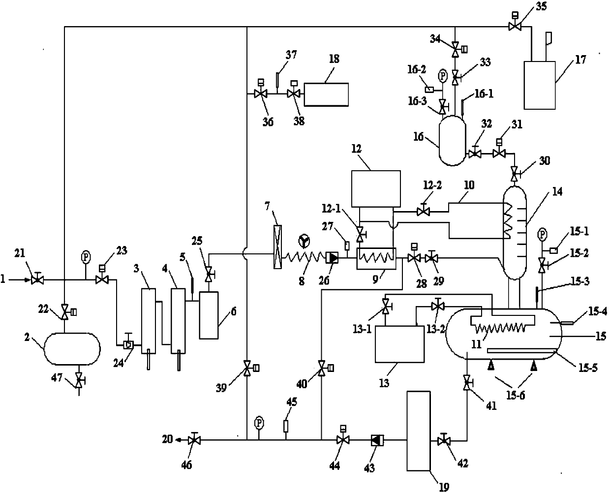
[0021] Specific implementation mode one: combine figure 1 , this embodiment is a separation and purification treatment device for sulfur hexafluoride and nitrogen mixed gas, which consists of a mixed gas inlet pipe 1, a primary dryer 3, a secondary dryer 4, a first pressure sensor 5, and a mesh filter 6 , compressor 7, air cooler 8, first heat exchanger 9 of -40°C refrigeration unit 12, second heat exchanger 10 of -40°C refrigeration unit 12, third heat exchanger of -80°C refrigeration unit 13 11. Rectification tower 14, purification tank 15, second buffer tank 16, liquid filling machine 19 and gas outlet pipe 20; mixed gas inlet pipe 1 and manual ball valve C 1 The inlet port of 21 is connected, the manual ball valve C 1 The outlet port of 21 is connected with the solenoid valve V 2 23 inlet port is connected to the manual ball valve C 1 21 with solenoid valve V 2 There is a pressure gauge between 23, solenoid valve V 2 The outlet port of 23 and the regulator valve F 1 ...

specific Embodiment approach 2

[0027] Embodiment 2: The difference between this embodiment and Embodiment 1 is that the solenoid valve V 7 34 outlet port and solenoid valve V 9 The inlet port of 39 is respectively connected with the solenoid valve V 10 The inlet port of 35 is connected, the solenoid valve V 10 The outlet end of 35 is connected with lye tank 17; Described lye tank 17 is PVC material, and volume is 60L, and interior dress 5% sodium hydroxide solution. Others are the same as in the first embodiment.

[0028] The lye tank 17 is used for the absorption of harmful substances in the gas when the gas is discharged.

specific Embodiment approach 3

[0029] Embodiment 3: The difference between this embodiment and Embodiment 1 or 2 is that the solenoid valve V 7 34 outlet port and solenoid valve V 9 The inlet port of 39 is respectively connected with the solenoid valve V 8 One end of 36 is connected, the solenoid valve V 8 The other end of 36 and angle solenoid valve A 1 One end of 38 is connected to the solenoid valve V 8 36 and angle solenoid valve A 1 A vacuum pressure sensor 37 is arranged between 38, and the angle solenoid valve A 1 The other end of 38 is connected with the vacuum pump 18; the vacuum pump 18 is a two-stage rotary vane type with an oil return solenoid valve, the ultimate vacuum degree is less than 0.05Pa, and the flow rate is greater than 60m 3 / h. Others are the same as in the first or second embodiment.

[0030] The vacuum pump (18) is used to evacuate the steel cylinder and the system in the device.


PUM


Abstract

The invention discloses a device and method for separating and purifying mixed gas of sulfur hexafluoride and nitrogen, relates to a device and method for separating and purifying mixed gas and solves the problems that in the prior art the mixed gas of SF6 and N2 cannot be separated and SF6 cannot be recycled. The device is composed of a mixed gas inlet pipe, a buffer tank, a dryer, a pressure sensor, a mesh type filter, a compressor, an air cooler, a heat exchanger, a refrigerating machine unit, a rectifying tower, a purifying tank, a lye tank, a vacuum pump, a liquid filling machine and a gas outlet pipe. The method comprises the following steps: recycling the mixed gas into the purifying tank, solidifying SF6, pumping out N2 from the purifying tank, heating SF6 in the purifying tank, filling SF6 in the purifying tank and testing the quality of the SF6 after treatment. The device and method disclosed by the invention are used for separating and purifying the mixed gas of sulfur hexafluoride and nitrogen.

Description

technical field [0001] The invention relates to a mixed gas separation and purification treatment device and a method for purifying and treating the mixed gas. Background technique [0002] SF 6 Gas is an important insulating medium, and is widely used in high-voltage electrical equipment for its excellent insulating properties and arc-extinguishing properties. But in practice SF 6 Gas also has some disadvantages in application. SF 6 The gas belongs to the high greenhouse effect gas, and its greenhouse effect index is CO 2 23,900 times that of carbon dioxide, and is listed as one of the six restricted greenhouse gases by the Kyoto Protocol. SF 6 It is a heavy gas with a large molecular weight, and its liquefaction temperature is higher than that of ordinary gases. It is easy to liquefy in an environment with high pressure and low temperature, so it is not suitable for alpine regions. Also SF 6 Gas is expensive and not suitable for electrical equipment that consumes a...

Claims


Application Information

Patent Timeline
IPC IPC(8): B01D53/00C01B17/45C07C19/08
CPCY02P20/151
Inventor 李国兴姜子秋关艳玲付丽君王磊
Owner STATE GRID CORP OF CHINA
Why Eureka
Try Eureka