Continuously-viable cutting drilling machine

A technology of stepless speed regulation and cutting mechanism, used in rotary drilling rigs, drilling equipment, earth-moving drilling, etc., can solve the problems of large belt replacement workload, increased cost, difficult installation, etc., and achieve the best drilling efficiency. , Improve the service life, the effect of convenient disassembly and replacement

Inactive Publication Date: 2014-12-10
GUILIN HUALI HEAVY INDS
View PDF7 Cites 0 Cited by
  • Summary
  • Abstract
  • Description
  • Claims
  • Application Information

AI Technical Summary

Problems solved by technology

[0003] (1) Existing cutting drilling rigs only have a fixed speed and torque for the drill pipe, but the actual working conditions of cutting drilling are very complicated, and the rock hardness is different in different areas. Even if the rock hardness is different in the same area, the required speed and torque are also different. different
Fixed RPM and torque in some formations can result in wasted energy, increased cost or inefficiency, increased bit wear
[0004] (2) The engine speed and main pump flow rate of existing cutting drilling rigs cannot be adjusted according to the load, resulting in energy loss, which is not energy-saving and environmentally friendly
When the cutting drilling rig is not operated for a long time in the drilling gap, the engine is still running at high speed, resulting in high fuel consumption and increased use costs
[0005] (3) The air compressor is driven by the engine through the pulley. The main head of the air compressor is installed in the engine cover. The structure is complex and the working environment temperature is high. The service life of the air compressor head and belt is short, and the workload of belt replacement is large. And the installation is difficult, time-consuming and labor-intensive
[0006] (4) The limit sleeve is short and has poor guiding performance. The drill pipe swings seriously during work, and the service life of the limit sleeve is short. When replacing the limit sleeve, the drill pipe must be removed before proceeding.

Method used


Image

  • Continuously-viable cutting drilling machine
  • Continuously-viable cutting drilling machine
  • Continuously-viable cutting drilling machine

Examples


Embodiment Construction

[0031] The principles and features of the present invention are described below in conjunction with the accompanying drawings, and the examples given are only used to explain the present invention, and are not intended to limit the scope of the present invention.

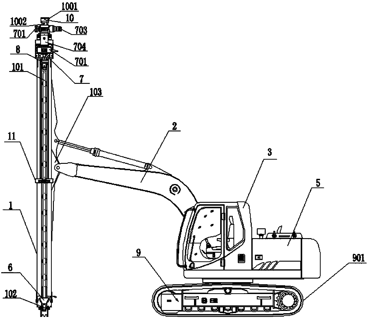
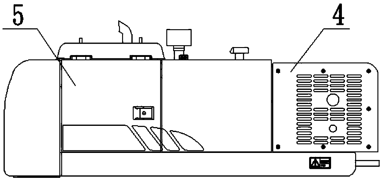
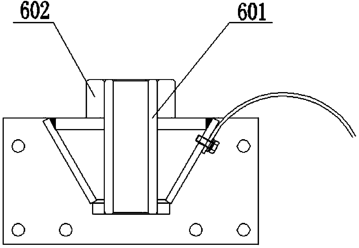
[0032] Such as figure 1 , figure 2 As shown, a cutting drill with stepless speed regulation includes a drill arm 1, a guide rail is provided on the drill arm 1, a chain, a sprocket for driving the chain, and a drill are arranged in the inner cavity of the drill arm 1. The rod 101 and the drill bit 102 connected to the bottom end of the drill rod 101 also include a boom 2, a cab 3, an air compressor 4, a platform assembly 5, a drill rod limiter 6, a cutting mechanism 7 and a rod supporter 11, One end of the boom 2 is rotatably connected to the middle part of the drill boom 1 through the drill boom connecting block 103, and the other end is connected to the front end of the cab 3, and the cab 3 and the air compresso...


PUM


Abstract

The invention relates to a continuously-viable cutting drilling machine. The continuously-viable cutting drilling machine comprises a drill boom. A guide rail, a chain, a chain wheel, a drill pipe and a drill bit are arranged on the drill boom. The continuously-viable cutting drilling machine further comprises a movable arm, a cab, an air compressor, a platform assembly, a drill rod snubber and a cutting mechanism. The drill rod snubber and the cutting mechanism are arranged at the two ends of the drill boom respectively. The cutting mechanism comprises a power head, a brake, a feeding motor and a cutting motor. The feeding motor is used for providing downward-pressure for the drill pipe to feed and lift the drill pipe during drilling, the cutting motor is used for driving the drill pipe to rotate and providing the cutting torque needed in the drilling process, and the power head carries out transmission through a gear to reduce the rotating speed of the cutting motor, improve the output torque and output appropriate drilling rotating speed and the appropriate cutting torque to the drilling pipe so that the optimal drilling working efficiency can be improved and the loss of the drill bit can be lowered. By means of a guiding and limiting sleeve of the drill rod snubber, the drill pipe carries out operation stably and slightly moves up and down during working, the service life of the guiding and limiting sleeve is prolonged, the guiding and limiting sleeve is convenient to dismount and replace, and when abraded, the guiding and limiting sleeve can be replaced by taking down the drill bit.

Description

technical field [0001] The invention relates to the field of drilling machines, in particular to a cutting drilling machine capable of stepless speed regulation. Background technique [0002] Existing cutting drills have the following deficiencies: [0003] (1) Existing cutting drilling rigs only have a fixed speed and torque for the drill pipe, but the actual working conditions of cutting drilling are very complicated, and the rock hardness in different areas is different. Even if the rock hardness in the same area is also different, the required speed and torque are also different. different. Using fixed speed and torque in some rock formations can result in wasted energy, increased cost or inefficiency, and increased bit wear. [0004] (2) The engine speed and main pump flow rate of existing cutting drilling rigs cannot be adjusted according to the load, resulting in energy loss, which is not energy-saving and environmentally friendly. When the cutting drilling rig is ...

Claims


Application Information

Patent Timeline
Patent Type & Authority Applications(China)
IPC IPC(8): E21B7/02E21B3/02
Inventor 周夏南陈宗宜蒋权赵慧
Owner GUILIN HUALI HEAVY INDS
Why Eureka
Try Eureka