Bipolar electrode electrogenerated chemiluminescence paper based micro-fluidic chip and imaging sensing application thereof

A microfluidic chip, electrochemistry technology, applied in the direction of chemiluminescence/bioluminescence, analysis through chemical reaction of materials, chemical instruments and methods, etc., can solve the problem of high requirements for detection equipment, expensive gold materials, etc. and other problems, to achieve the effect of reducing signal interference, low equipment price, and simple processing technology

Active Publication Date: 2014-12-10
SOUTH CHINA NORMAL UNIVERSITY
View PDF7 Cites 18 Cited by
  • Summary
  • Abstract
  • Description
  • Claims
  • Application Information

AI Technical Summary

Problems solved by technology

However, this sensing and detection technology has the disadvantages of expensive gold materials, com

Method used


Image

  • Bipolar electrode electrogenerated chemiluminescence paper based micro-fluidic chip and imaging sensing application thereof
  • Bipolar electrode electrogenerated chemiluminescence paper based micro-fluidic chip and imaging sensing application thereof
  • Bipolar electrode electrogenerated chemiluminescence paper based micro-fluidic chip and imaging sensing application thereof

Examples


Example Embodiment

[0030] Example 1

[0031] A method for preparing a double-electrode electrochemiluminescent paper-based microfluidic chip includes the following steps:

[0032] (1) Use Adobe Illustrate CS5 software to design the microfluidic channel (including solution storage tank) and electrode (including working electrode and driving electrode) patterns, and process the microfluidic channel screen and drive electrode screen by the manufacturer.

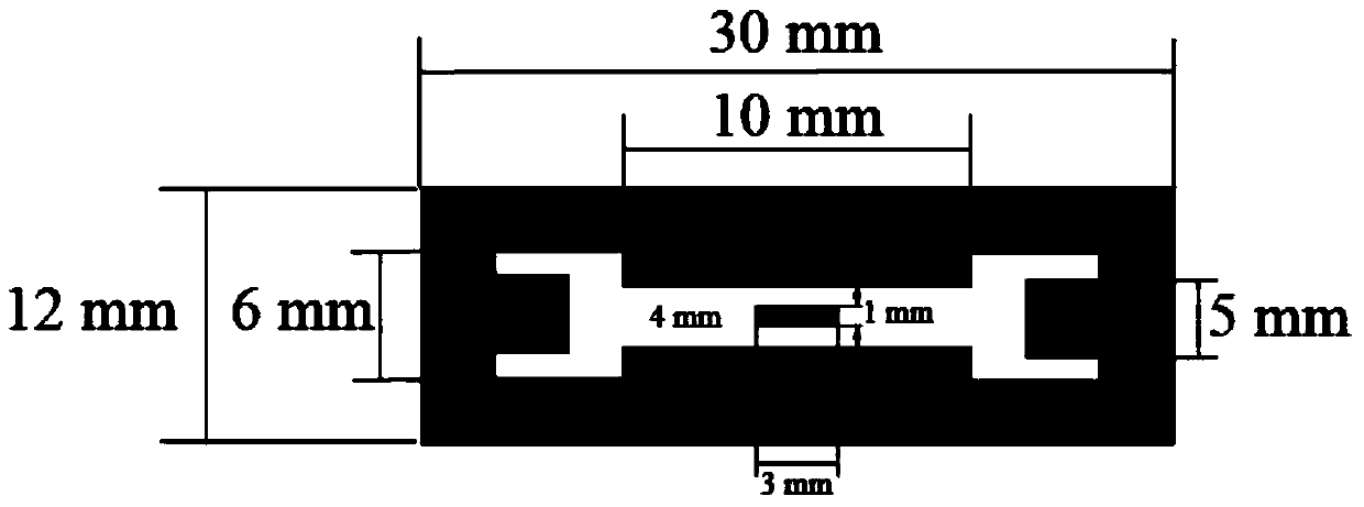
[0033] The size of the microfluidic channel is 10×4mm, the size of the driving electrode is 5×5mm, the size of the working electrode is 3×1mm, and the size of the entire paper-based microfluidic chip is 30×12mm. Detailed chip size such as figure 1 Shown.

[0034] (2) First, cut the No. 1 Whatman filter paper into a size suitable for the channel screen. Then the conductive carbon paste is used as the material, and the electrode is screen printed on the filter paper through the electrode screen. After printing, the electrodes are baked in an oven at 100°C...

Example Embodiment

[0037] Example 2

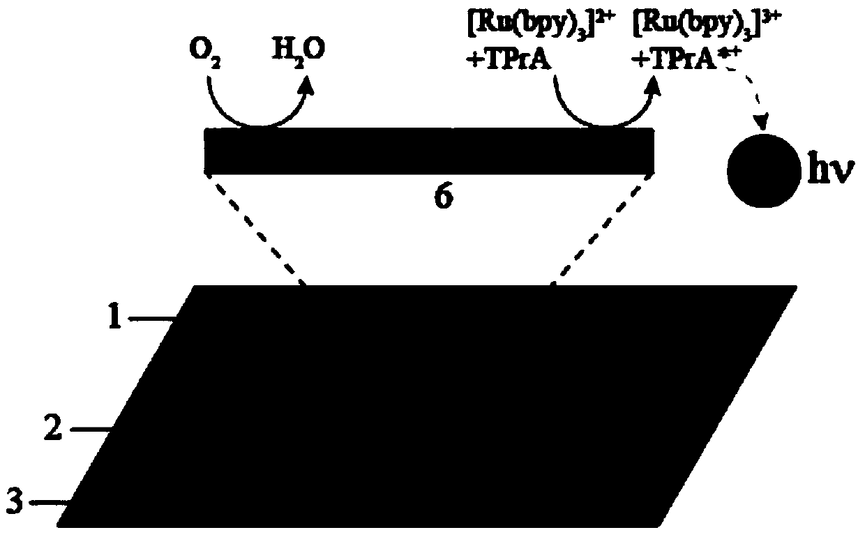
[0038] The paper-based microfluidic chip prepared in Example 1 was used in Ru(bpy) 3 2+ The ECL system to detect TprA includes the following steps:

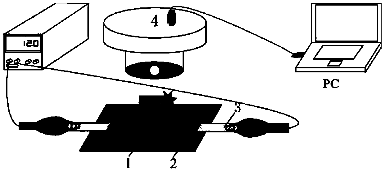
[0039] (1) Put the microfluidic chip in a dark box containing a CCD camera, such as image 3 Shown; Use conductive tape to connect the drive electrode to the power supply, and use a clip to clamp both ends of the chip to make it hang in the air for testing;

[0040] (2) Use PBS buffer with pH 6.9 to mix Ru(bpy) 3 2+ Prepare a solution with a concentration of 2 mM, and at the same time use PBS buffer to prepare TprA at different concentrations, including 2000, 1000, 500, 200, 100, 50, 20 μM. Before the test, the TprA solution and Ru(bpy) 3 2+ The solution is mixed with a volume ratio of 1:1 to obtain Ru(bpy) 3 2+ And TprA mixed solution;

[0041] (3) Pipette 15μL of prepared reaction solution (i.e. containing Ru(bpy) 3 2+ And TprA mixed solution), dripped into the chip channel, after 0.5min, the reaction solution filled...


PUM


Abstract

The invention discloses a bipolar electrode electrogenerated chemiluminescence paper based micro-fluidic chip and the application thereof to imaging sensing. The preparation method of the chip comprises the following steps: designing patterns of a micro-fluidic channel and an electrode through software and then manufacturing screens, clinging the electrode screen onto filter paper, printing the shape and the size of the electrode on the filter paper by brushing conductive carbon paste on the electrode screen, taking the filter paper on which the electrode is printed, clinging the channel screen onto filter paper, performing grinding and brushing on the channel screen through a wax pencil, then performing heating, so as to ensure that wax penetrates through the filter paper to form the micro-fluidic channel and a solution storage tank, and obtaining the bipolar electrode electrogenerated chemiluminescence paper based micro-fluidic chip. The chip takes the carbon paste as bipolar electrode material on paper for the first time, an electrogenerated chemiluminescence chip manufactured by taking the chip as a basis performs imaging sensing detection on tripropylamine, and the chip has the advantages of bipolar electrode electrochemistry and paper based microfluidics.

Description

technical field [0001] The invention belongs to the field of microfluidic chip sensing, and in particular relates to a paper-based microfluidic chip with amphoteric electrode electrochemiluminescence and its application in imaging sensing. Background technique [0002] In recent years, microfluidic chips used for biochemical and medical testing can significantly reduce reagent consumption, are inexpensive, and can greatly improve analysis efficiency. Due to these advantages, microfluidic chip technology has developed very rapidly, and has shown great application potential in the fields of analytical chemistry, food hygiene, environmental monitoring, biology, and medicine. With the demand of the market, researchers are increasingly looking for microfluidic chips with low price, small size, light weight, simple operation, good stability, fast detection speed and high sensitivity, especially for relatively poor areas in developing countries and Microfluidic chips for medical t...

Claims


Application Information

Patent Timeline
IPC IPC(8): G01N21/76B01L3/00
Inventor 章春笋刘瑞
Owner SOUTH CHINA NORMAL UNIVERSITY
Why Eureka
Try Eureka