Direct-drive wind power conversion structure based on MMC and bipolar direct-current transmission structure

A DC transmission, bipolar technology, applied in the conversion of AC power input to AC power output, wind power generation, output power conversion devices, etc., can solve the problems of power device heating, system cost increase, system efficiency reduction, etc., to achieve Effects of low switching loss, space saving, and simple topology

Inactive Publication Date: 2014-12-24
周细文 +1
View PDF2 Cites 12 Cited by
  • Summary
  • Abstract
  • Description
  • Claims
  • Application Information

AI Technical Summary

Problems solved by technology

[0005] In the parallel converter system, there will be a serious circulation problem; the circulation flows between the parallel converters, and its existence increases the loss, reduces the system efficiency, and causes serious heat generation of power devices, and even burns them out; There are two ways to solve the circulating current problem in the parallel converter system: one is to eliminate the circulating current channel on the hardware, and the other is to use an appropriate control method to suppress the circulating current; usually the method of eliminating the circulating current by hardware is to add an isolation transformer, which can Block the circulating current circuit on the AC side to eliminate circulating currents. At the same time, using isolation transformers with different forms of secondary structure can eliminate specific harmonics and reduce pollution to the power grid; The weight is very large, which will increase the cost of the system, so it is not suitable for high-power permanent magnet or electric excitation direct drive wind power system

Method used


Image

  • Direct-drive wind power conversion structure based on MMC and bipolar direct-current transmission structure
  • Direct-drive wind power conversion structure based on MMC and bipolar direct-current transmission structure
  • Direct-drive wind power conversion structure based on MMC and bipolar direct-current transmission structure

Examples


Embodiment 1

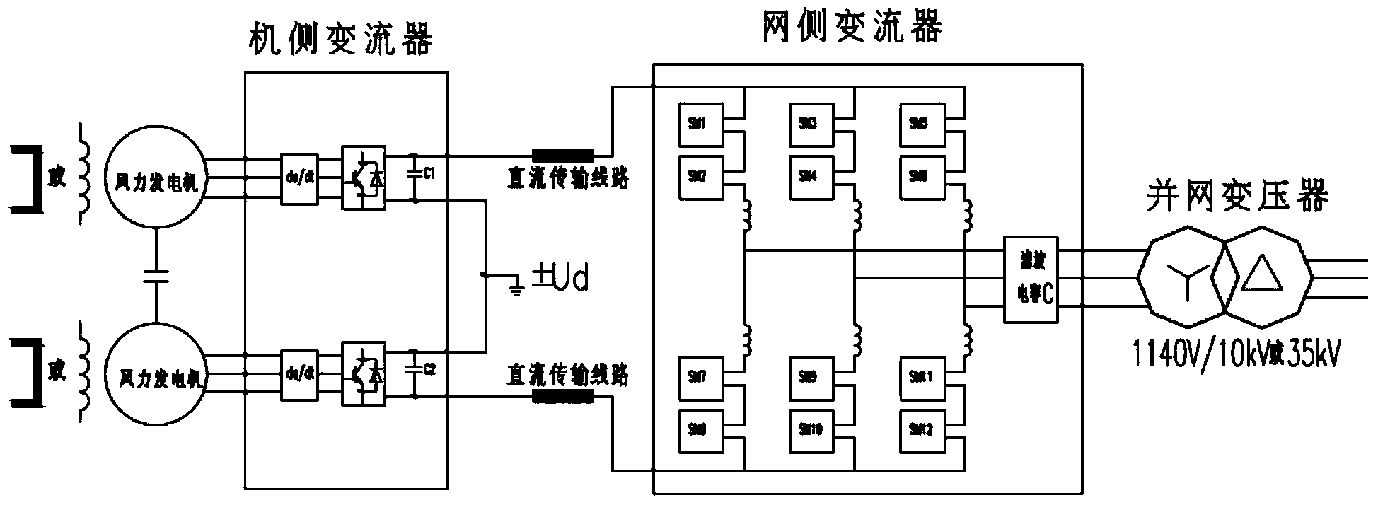
[0031] Such as figure 1As shown, this embodiment provides a direct-drive wind power conversion structure based on MMC and bipolar DC transmission structure, including two direct-drive wind generators, machine-side converters, grid-side converters and grid-connected The transformer and the machine-side converter are composed of two independent rectification circuits, each rectification circuit includes a du / dt filter, a controllable rectifier, and a DC capacitor, and the rectification input terminals are respectively connected to two single-winding electric excitation direct drive The wind turbine is connected to rectify the three-phase AC generated by the wind turbine into a DC voltage. The four rectification circuits are connected in parallel with the two outputs of the motor, and then grounded in series, so that the entire machine-side converter outputs a bipolar DC voltage. ;

[0032] The grid-side converter is mainly composed of three groups of modular multilevel converte...

Embodiment 2

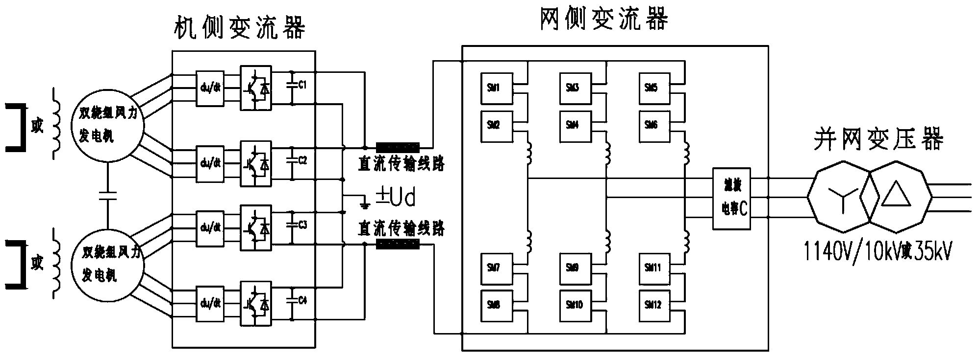
[0035] Such as figure 2 As shown, this embodiment provides a direct-drive wind power conversion structure based on MMC and bipolar DC transmission structure, including two direct-drive wind generators, machine-side converters, grid-side converters and grid-connected The transformer and the direct-drive wind turbine are double-winding direct-drive wind turbines, and each set of three-phase windings is set independently. The output end of each set of three-phase windings is connected in series with a du / dt filter and a rectifier, that is, each set of two-phase The winding direct drive wind turbine is connected with two du / dt filters and two rectifiers;

[0036] The positive DC output terminals of the two rectifiers connected to the first double-winding direct-drive wind turbine are connected in series with the first DC resistor and then connected to the grid-side converter through the positive DC transmission line. The negative DC output terminals of the two connected rectifie...

Embodiment 3

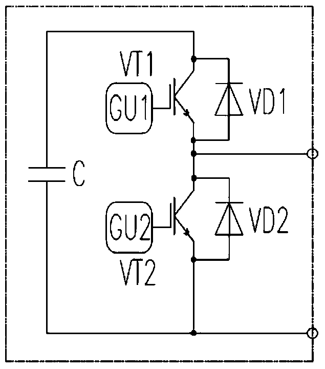
[0039] Such as image 3 As shown, in this embodiment, the SM sub-module adopts a half-bridge structure, which is composed of 2 insulated gate bipolar transistors IGBT and 1 DC energy storage capacitor, and the IGBTs are respectively connected in parallel with a reverse diode VD, by controlling VT1 and VT2 Turning on and off can realize the state of putting in, cutting out and blocking of the sub-module. Further reasoning, at any time, the output of AC voltage can be adjusted by adjusting the number of sub-modules invested in the upper and lower bridge arms, and at the same time, the number of sub-modules invested in each phase unit remains constant to maintain a constant DC voltage, so MMC The number of output levels is n+1; the inverter modulates the DC voltage rectified by the machine-side converter into an AC three-phase voltage, and realizes the three-phase AC voltage by controlling the on and off of the switching devices of each power unit Synthesis, connected to the gri...


PUM


Abstract

The invention discloses a direct-drive wind power conversion structure based on an MMC and a bipolar direct-current transmission structure. The direct-drive wind power conversion structure comprises two direct-drive wind power generators, a machine side converter, a network side converter and a grid-connected transformer. The machine side converter is composed of two independent rectifying circuits, and each rectifying circuit comprises a du / dt filter, a controllable rectifier and a direct-current capacitor. The network side converter mainly comprises three groups of modular multi-level converters (MMCs). The direct-drive wind power conversion structure comprises twelve standard power unit submodules (SM) totally. The bipolar direct-current structure is adopted in the direct-drive wind power conversion structure based on the MMC and the bipolar direct-current transmission structure, so that when single-pole direct-current faults happen to a direct-current line, a fault pole rectification side converter shuts, and direct current output by a fault pole rectification side drops to zero, and in other words, no overcurrent causing the direct-current faults is generated.

Description

technical field [0001] The invention relates to the field of wind power generation, in particular to a direct-drive wind power conversion structure based on MMC and a bipolar DC transmission structure. Background technique [0002] The power of wind turbines continues to increase. At present, high-power wind turbines mostly use six-phase (double-winding) motors, which output two sets of three-phase voltages (wrong phase or wrong phase), and the capacity of each set is half of the capacity of the motor; in wind power generation Among the various schemes, the direct-drive wind power generation method has increasingly become a research and application hotspot due to its superior performance; the existing large-capacity direct-drive wind power generators, due to the limitation of the tip speed ratio, the increase of capacity will lead to With the decrease of generator speed, the diameter and other dimensions of low-speed and large-capacity direct-drive wind turbines will become ...

Claims


Application Information

Patent Timeline
Patent Type & Authority Applications(China)
IPC IPC(8): H02J3/38H02M5/458
CPCY02E10/76
Inventor 周细文吕笑岩刘景芝章辉陈烘民黄庆利
Owner 周细文
Why Eureka
Try Eureka