Solar cell, method for producing solar cell, and solar cell module

A technology of solar cells and manufacturing methods, applied in the direction of electrical components, final product manufacturing, sustainable manufacturing/processing, etc., can solve problems such as complicated processes, and achieve the effect of easy electrode formation and excellent photoelectric conversion characteristics

Inactive Publication Date: 2014-12-31
MITSUBISHI ELECTRIC CORP
View PDF3 Cites 2 Cited by
  • Summary
  • Abstract
  • Description
  • Claims
  • Application Information

AI Technical Summary

Problems solved by technology

However, such a method of locally changing the surface shape on the light-receiving surface side of the semiconductor substrate becomes complicated in process, and cannot be said to be a method suitable for mass production.

Method used


Image

  • Solar cell, method for producing solar cell, and solar cell module
  • Solar cell, method for producing solar cell, and solar cell module
  • Solar cell, method for producing solar cell, and solar cell module

Examples


Embodiment approach 1

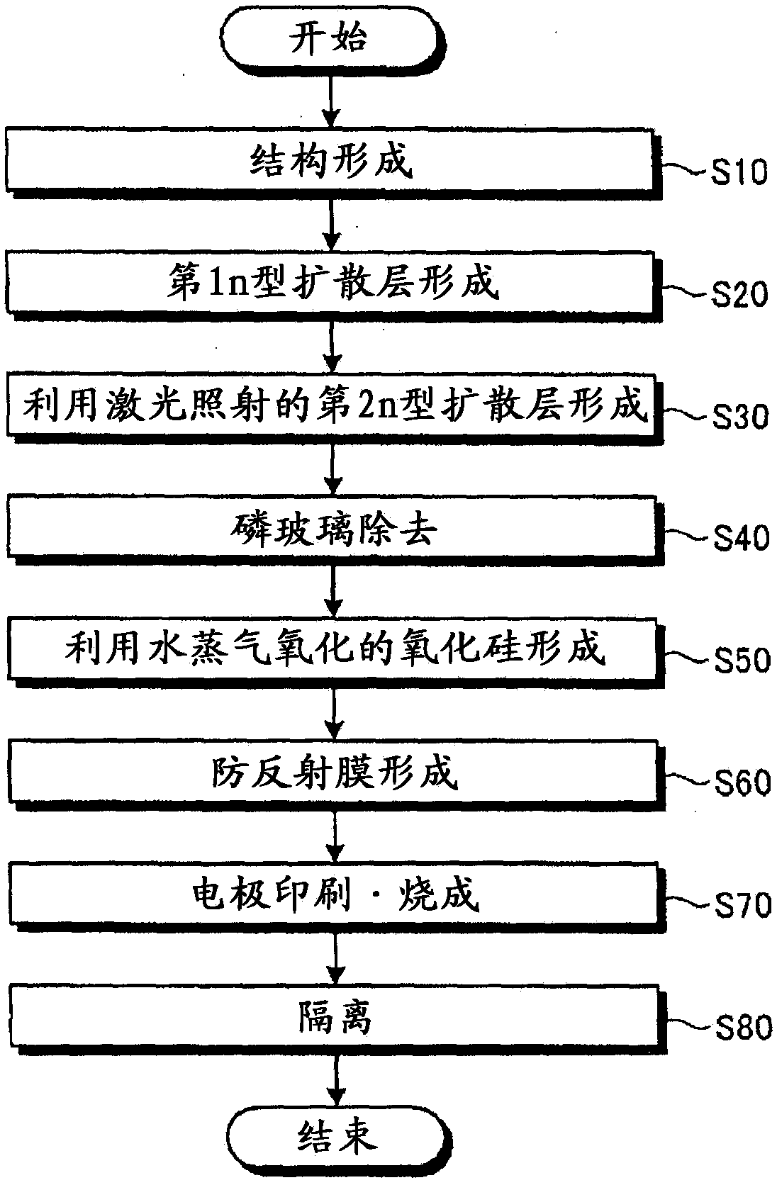
[0038] figure 1 It is a flowchart for explaining an example of the manufacturing process of the solar battery cell concerning Embodiment 1 of this invention. Figure 2-1 to Figure 2-9 It is a cross-sectional view of main parts for explaining an example of the manufacturing process of the solar cell according to Embodiment 1 of the present invention. image 3 It is a main part perspective view which shows the schematic structure of the solar battery cell concerning Embodiment 1 produced by the manufacturing method of the solar battery cell concerning Embodiment 1. FIG. be explained, although in figure 1It is not described in the following descriptions, but immersion treatment in hydrofluoric acid and water washing treatment for the purpose of wafer cleaning treatment and natural oxide film removal are performed as necessary between each process.

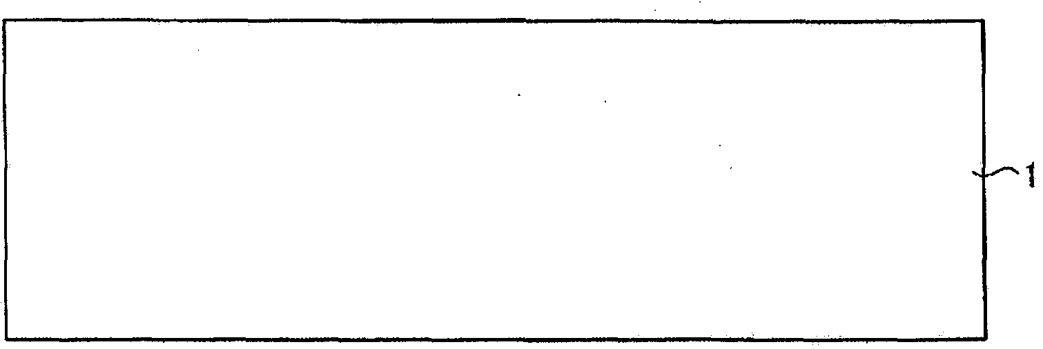
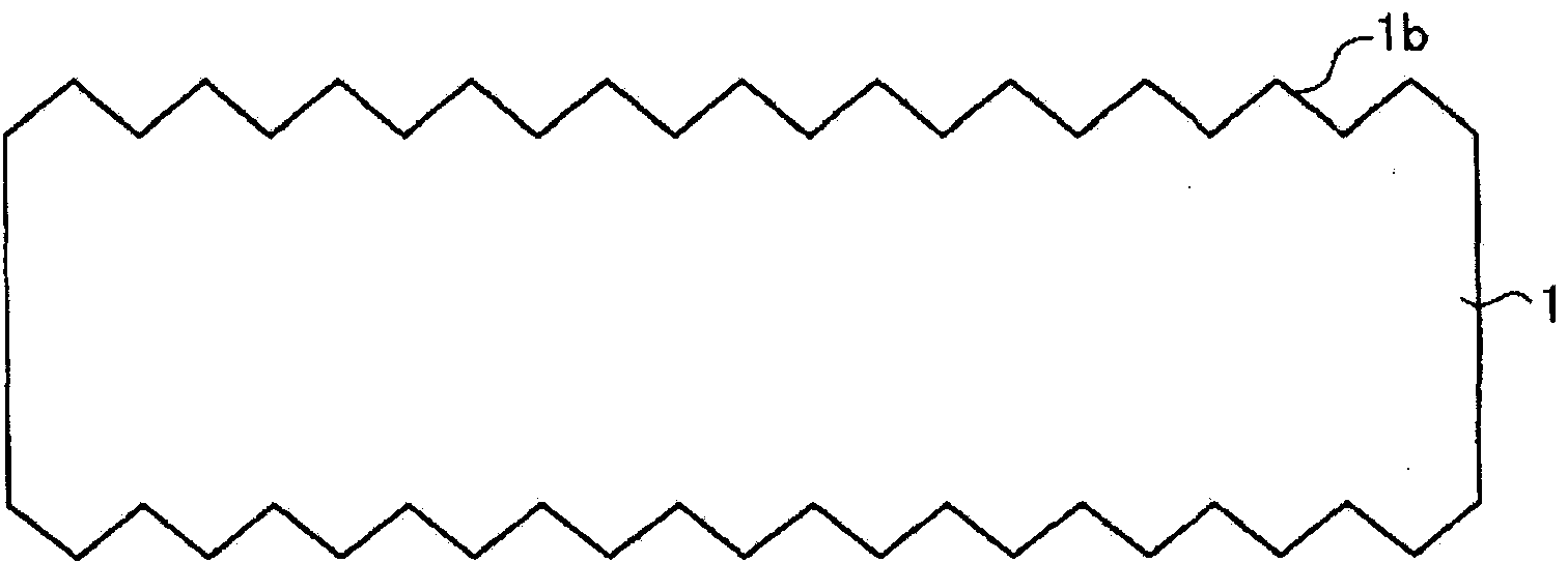
[0039] First, as a semiconductor substrate, for example, a p-type monocrystalline silicon substrate (hereinafter referred to as a ...

Embodiment approach 2

[0092] Figure 8 It is a flowchart for explaining an example of the manufacturing process of the solar battery cell concerning Embodiment 2 of this invention. Although the case of removing the phosphorous glass after laser irradiation was described in Embodiment 1, the sequence of laser irradiation and phosphorous glass removal is not limited to this. The order of laser irradiation and phosphorous glass removal may be reversed, that is, laser irradiation is performed after phosphorous glass is removed.

[0093] When using phosphorus oxychloride (POCl 3 ) after thermal diffusion of the gas, phosphorus (P) that has not been electrically activated (inactive) exists on the surface of the silicon substrate. When laser irradiation is performed in this state, inactive phosphorus (P) is activated by laser irradiation, and the activated phosphorus (P) diffuses into a deeper region of the silicon substrate to form an SE structure. Thereafter, when the silicon substrate is subjected t...


PUM


Abstract

A solar cell comprises a first conduction-type semiconductor substrate having on one surface a second conduction-type impurity-diffusing layer wherein impurity elements are diffused; a passivation film formed on the impurity-diffusing layer from an oxide film of the material in the semiconductor substrate; an anti-reflection film formed on the passivation film from a translucent material having a refractive index different from that of the oxide film; a light-receiving front surface electrode that is connected electrically to the impurity-diffusing layer and is formed on the one surface of the semiconductor substrate; and a back surface electrode formed on the other surface of the semiconductor substrate. The impurity-diffusing layer is formed from a first impurity-diffusing layer, which is the light-receiving region and contains impurity elements at a first concentration, and a second impurity-diffusing layer, which is the lower region of the light-receiving front surface electrode and contains impurity elements at a second concentration higher than the first concentration, wherein the surface state of the first impurity-diffusing layer and second impurity-diffusing layer is the same and the thickness of the passivation film on the second impurity-diffusing layer is thinner than the film thickness of the passivation film on the first impurity-diffusing layer.

Description

technical field [0001] The present invention relates to a solar cell, a method for manufacturing the solar cell, and a solar cell module. Background technique [0002] In order to increase the efficiency of solar cells, it is necessary to suppress the recombination of carriers, and one of the methods for this is the Selective Emitter (hereinafter referred to as SE) structure. A general crystalline silicon (Si) solar cell structure is such that an antireflection film is formed on the photoelectric conversion part where the pn junction is formed, a comb-shaped electrode is arranged on the surface (light-receiving surface), and a full-surface electrode is arranged on the back. structure. Such a solar cell is called a homogeneous emitter cell (hereinafter referred to as an HE cell). [0003] In terms of the characteristics of solar cells, it is known that the impurity concentration on the outermost surface of the light-receiving region (the interface between the anti-reflectio...

Claims


Application Information

Patent Timeline
Patent Type & Authority Applications(China)
IPC IPC(8): H01L31/0224H01L31/0352H01L31/18
CPCH01L31/022425H01L31/068H01L31/1804Y02E10/547H01L31/0224H01L31/18Y02P70/50H01L31/02168H01L31/02366H01L31/065H01L31/1864H01L31/1868
Inventor 西本阳一郎
Owner MITSUBISHI ELECTRIC CORP
Why Eureka
Try Eureka