An oil shale dry distillation shale oil and gas phase state separation device

A technology for separation of shale oil, gas and phase state, applied in the field of oil shale dry distillation, can solve the problems of difficulty in ensuring the quality of shale oil, dust blockage in the condensation recovery system, and inability to remove oil and gas shale ash dust, etc., to achieve high-efficiency separation , The effect of improving quality and preventing sludge from returning

Inactive Publication Date: 2015-11-18
NORTHEAST DIANLI UNIVERSITY
View PDF9 Cites 0 Cited by
  • Summary
  • Abstract
  • Description
  • Claims
  • Application Information

AI Technical Summary

Problems solved by technology

Among them, on the Galoter furnace type, the method of continuously setting cyclone dust collectors can reduce some shale dust particles, but it is still unable to remove the fine shale dust in the oil and gas, which will easily lead to dust blockage in the condensation recovery system, and it is also difficult Guarantee the quality of shale oil; on the Tosco furnace type, by introducing an external solid heat carrier (ceramic heating ball) instead of shale ash for circulation heating, although the shale can be effectively heated, under the action of the roller, the collision between the ball and the shale Fine shale ash is still formed and wrapped on the surface of the heating sphere, which is recycled back to the heating furnace and is still mixed in the retorted shale oil and gas, which is also difficult to guarantee the quality of shale oil

Method used


Image

  • An oil shale dry distillation shale oil and gas phase state separation device
  • An oil shale dry distillation shale oil and gas phase state separation device
  • An oil shale dry distillation shale oil and gas phase state separation device

Examples


Embodiment Construction

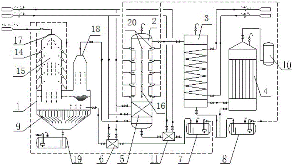
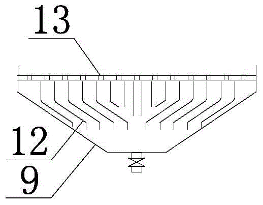
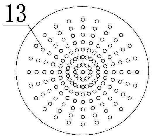
[0029] The present invention will be further described below using the accompanying drawings and examples.

[0030] refer to Figure 1-Figure 6, a kind of oil shale dry distillation shale oil-gas phase state separation device of the present invention, comprises: heavy oil washing separation tank 1, light oil washing separation tank 2, light oil intercooling separation tank 3, electrostatic oil trap 4 , Indirect cooling heat exchanger for medium temperature 5, Indirect cooling heat exchanger for high temperature 6, Heavy oil washing circulation tank 7, Light oil washing circulation tank 8, Sludge deposition tank 9, Gas collection tank 10, Low temperature use Indirect cooling heat exchanger 11, heavy oil wash impact flow resistance body 15, light oil wash impact flow resistance body 16 and sludge tank 19. The top of the heavy oil washing separation tank 1 is provided with a high-temperature ash-containing shale oil gas inlet 17, the right side of the heavy oil washing separatio...


PUM


Abstract

The invention provides a shale oil-gas-phase separating device for oil shale distillation. The shale oil-gas-phase separating device is characterized by comprising a heavy oil washing separation tank, an oil sludge deposition tank, a heavy oil washing circulation tank, a heavy oil sludge tank, a light oil washing separation tank, a light oil intercooling separation tank, a moderate-temperature using intercooling heat exchanger, a high-temperature using intercooling heat exchanger, a low-temperature using intercooling heat exchanger, a light oil washing circulation tank, an electrostatic oil trap and a gas collection tank. The shale oil-gas-phase separating device can efficiently separate shale ashes from shale oil gas, separates heavy oil from light oil, separates gas, recycles heat of high-temperature shale oil gas, and fully utilizes self-distilled products without circulation of other external working media, so that energy consumption is reduced, and the yield and the quality of heavy oil, light oil of gasoline, light oil of light diesel oil and gas in the condensation and recovery processes of shale oil gas are improved. The shale oil-gas-phase separating device is wide in application range, and can be used for dry distillation of coal, oil sand, waste tires, petroleum coke, organic wastes and biomass.

Description

technical field [0001] The invention relates to the technical field of oil shale dry distillation, in particular to an oil shale dry distillation shale oil-gas phase separation device. Background technique [0002] Oil shale carbonization, that is, heating oil shale to the required temperature in an air-isolated environment, so that the kerogen undergoes pyrolysis reaction to generate shale oil and carbonization gas. Shale oil can not only be directly used as fuel for marine turbines Liquid fuels can also be produced through distillation and other processes to produce gasoline and diesel. At present, the commonly used technical devices mainly include gas heat carrier and solid heat carrier. Among them, the gas heat carrier carbonization device is heated by thermal cycle gas and heat generation gas to realize dry distillation. These two kinds of gases used for heating are a large amount. , the shale oil and gas generated by the oil shale retort process is more than ten times...

Claims


Application Information

Patent Timeline
Patent Type & Authority Patents(China)
IPC IPC(8): C10G5/00C10G53/02C10L3/10
CPCC10G5/00C10G53/02C10G2400/26C10L3/10
Inventor 王擎迟铭书左春玲崔达
Owner NORTHEAST DIANLI UNIVERSITY
Why Eureka
Try Eureka