
Radio frequency identification remote cable used for base station and manufacturing method thereof

A technology of wireless radio frequency and manufacturing method, which is applied in the direction of light guide, optics, optical components, etc., can solve the problems of not fully considering the distinguishability of internal sub-cables, not fully considering the distinguishable characteristics, and not being able to play a supporting role. Avoid the effect of unstable pay-off tension, constant tension and uniform force

Inactive Publication Date: 2015-01-07
FURUKAWA ELECTRIC XIAN OPTICAL COMM
View PDF6 Cites 12 Cited by
  • Summary
  • Abstract
  • Description
  • Claims
  • Application Information

AI Technical Summary

Problems solved by technology

The authorization number is CN203054298U, the name is radio frequency remote optical cable for base station, the authorization number is CN201622374U, and the name is wireless radio frequency remote unit optical cable, both adopt circular sheath structure, but do not fully consider the connection between the two ends of the optical cable in the later assembly The easy identification of the internal sub-cables during the device, the lack of full consideration of the easy identification characteristics of the remote optical cable during the construction of existing towers and later maintenance, and the anti-rat measures in the machine room and tower, and the improper manufacturing process of the remote optical cable have caused serious problems. Heat shrinkage (usually when the sheath is made of LSZH material, the heat shrinkage rate of the cable sheath at 85°C is between 2% and 3.5%), resulting in the problem of separation between the connecting device and the cable
At the same time, among the authorized patented products, the remote optical cable with filling components is made of aramid yarn extruded sheath structure. Very good support, so that when the optical cable is stretched and flattened, it is easy to be unevenly stressed due to structural instability, and even fiber breakage occurs

Method used


Image

  • Radio frequency identification remote cable used for base station and manufacturing method thereof
  • Radio frequency identification remote cable used for base station and manufacturing method thereof
  • Radio frequency identification remote cable used for base station and manufacturing method thereof

Examples


Embodiment 1

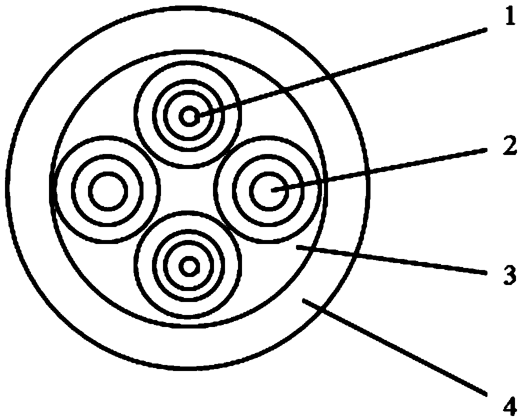
[0093] Such as figure 1 As shown, a wireless radio remote optical cable for a new base station, which includes a sub-cable 1, a filling member 2, a non-metal filling yarn 3, and a sheath 4;

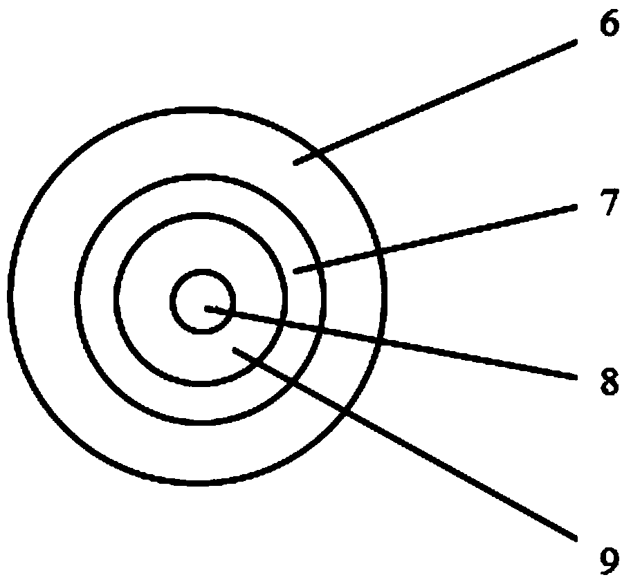
[0094] Wherein, the sub-cable is composed of an optical fiber 8, an optical fiber tight sleeve layer 9, a non-metallic reinforcing fiber yarn 7 and a sub-cable sheath 6;

[0095] Wherein, the optical fiber 8 is a B6 optical fiber specified in YD / T 1954, other single-mode optical fiber specified in GB / T 9771, or a multimode optical fiber specified in GB / T 12357.1, and the optical fiber may contain a colored and cured layer of 3 μm to 5 μm ;

[0096] Wherein, the optical fiber tight buffer layer 9 is made of thermoplastic materials such as LSZH or PVC, the outer diameter of the optical fiber tight buffer layer is 0.6mm or 0.9mm, the peeling force of the optical fiber tight buffer layer is ≤10N, and the color of the optical fiber tight buffer layer can be It is any color in the full color ...

Embodiment 2

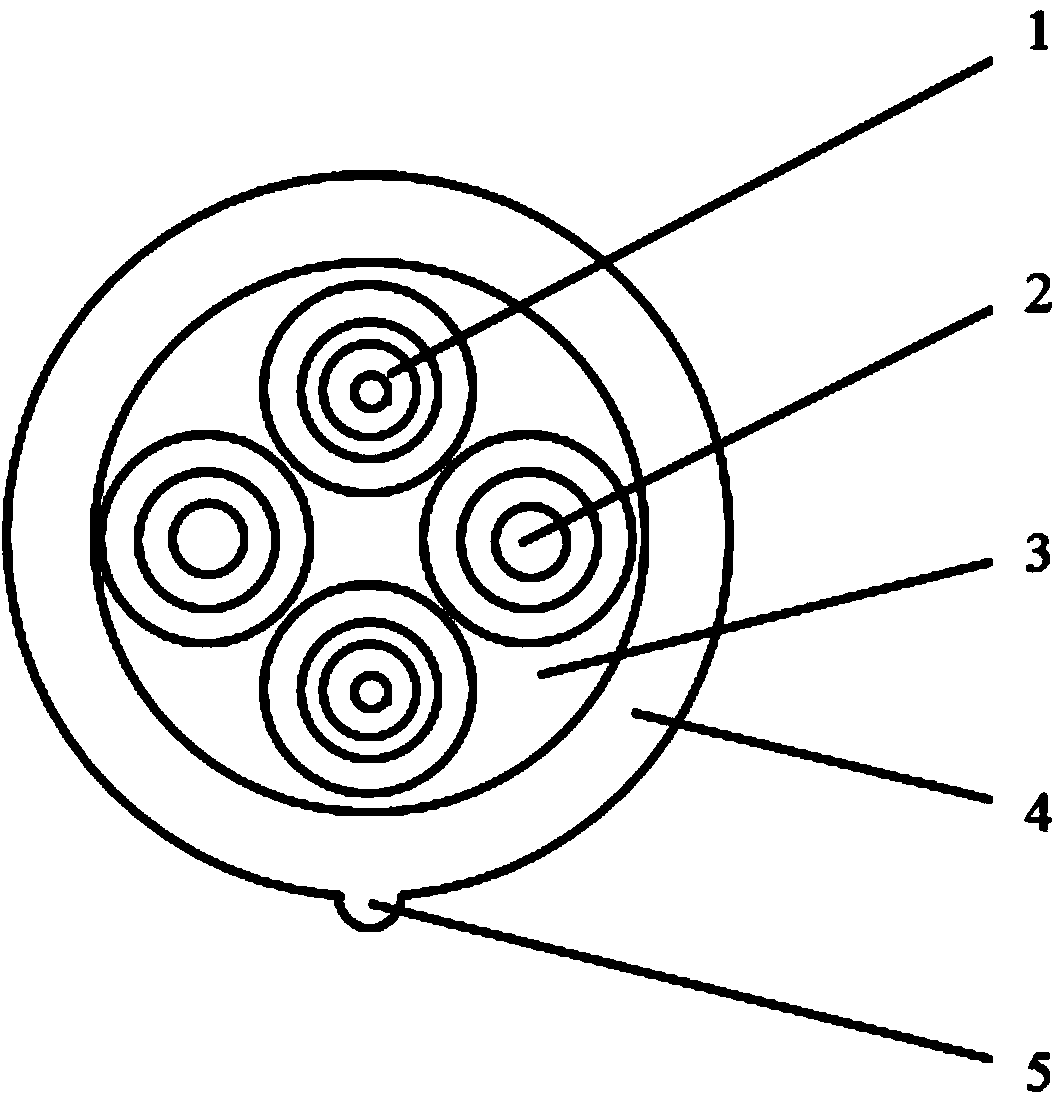
[0106] Such as figure 2 As shown, a radio frequency remote optical cable used for existing base stations. This optical cable is suitable for the construction of 3G / 4G base stations in existing 2G base stations, and can also be used for the construction of new base stations. It is different from Embodiment 1 in that the outer edge of the cylindrical sheath 4 of the optical cable is connected with a single or multiple touch identification marks 5 .

[0107] Wherein, the cylindrical sheath 4 and the touch sign 5 are produced synchronously on the machine.

[0108] Wherein, the shape of the touch mark 5 is a semicircle, a triangle or other simple shapes.

[0109] Wherein, the diameter of the semicircle is close to the outer edge of the cylindrical sheath 4, and the radius of the semicircle touch mark is 1.5mm-2.0mm.

[0110] Wherein, the bottom edge of the triangular touch mark is close to the outer edge of the cylindrical sheath 4, the apex angle of the triangular ...


PUM

PropertyMeasurementUnit
Elastic modulusaaaaaaaaaa
Thicknessaaaaaaaaaa

Abstract

The invention discloses a radio frequency identification remote cable used for a base station and a manufacturing method of the cable. The cable comprises a cable jacket, at least one subcable and at least one filling component, wherein the subcables and the filling components are arranged in the cable jacket, the cable jacket is further internally provided with nonmetallic filling yarns, and the outer surface of the cable jacket is provided with a touch identification mark. The manufacturing method comprises the steps of a, production of optical fibers, b, coloring of the optical fibers, c, tight sleeving of the optical fibers, d, formation of subcable jackets, e, formation of the filling components, f, twisting of a cable core, f, coating of the jacket and h, detection and delivery. The surface mark of the radio frequency identification remote cable used for the base station is clear, resistant to wear and falling off, and likely to be distinguished; the hot-shrinkage rate is small on the high-altitude and high-temperature condition, and it is ensured that the cable and the end of a connector are fastened and sealed; the mechanical performance is good, and a good ratproof effect is achieved; the assembly efficiency of the connector in a factory is improved effectively. The manufacturing process is easy to operate, and the production and development investment is low.

Description

technical field [0001] The invention belongs to the technical field of manufacturing optical cables for indoor and outdoor use, and relates to a radio frequency remote optical cable for a base station, a manufacturing method and a processing technology thereof. Background technique [0002] In the base station signal transmission system, from the base band unit BBU (Base Band Unit) to the remote radio unit RRU (Remote Radio Unit), the optical cable that provides signal transmission for the RRU is called a radio remote optical cable. The radio frequency remote optical cable is mainly used in the local remote at the same site, and the length is usually between 100 meters and 300 meters. [0003] With the increasing demand for mobile data services, the network is required to be able to provide high-speed data services and other value-added services based on data applications to a certain extent. The feature of lower traffic price has attracted people's attention. However, the...

Claims


Application Information

Patent Timeline
IPC IPC(8): G02B6/44
CPCG02B6/4482G02B6/4432G02B6/4476
Inventor 宋海燕张卫强刘少锋张义军王正刚朱勇张养柱申春磊
Owner FURUKAWA ELECTRIC XIAN OPTICAL COMM
Learn More