
A test device for thermal molding and curing deformation of resin-based composite materials and the preparation and use method of the device

A composite material, curing deformation technology, applied in the direction of measuring devices, optical devices, special recording/indicating devices, etc., can solve the problems of fragility and breakage of the gate area, inability to effectively transmit monitoring signals, and difficulty in detachment of fully rigid molds, etc., to achieve Conducive to demoulding, avoiding artificial large deformation, and easy to slip

Active Publication Date: 2017-08-01
SHANDONG UNIV
View PDF4 Cites 0 Cited by
  • Summary
  • Abstract
  • Description
  • Claims
  • Application Information

AI Technical Summary

Problems solved by technology

[0007] The purpose of the present invention is to overcome the above-mentioned deficiencies and provide a test device for thermal molding and curing deformation of resin-based composite materials and the preparation and use method of the device, so as to solve the problem of fragility and breakage of the gate area of ​​the FBG sensor when monitoring the thermal molding and curing deformation of composite materials Improper lead wires in the closed fully rigid thermal molding mold will cause the problem that the monitoring signal cannot be effectively transmitted. At the same time, it is difficult to disengage the composite material structural parts with the built-in FBG sensor and the fully rigid mold

Method used


Image

  • A test device for thermal molding and curing deformation of resin-based composite materials and the preparation and use method of the device
  • A test device for thermal molding and curing deformation of resin-based composite materials and the preparation and use method of the device
  • A test device for thermal molding and curing deformation of resin-based composite materials and the preparation and use method of the device

Examples


Embodiment 1

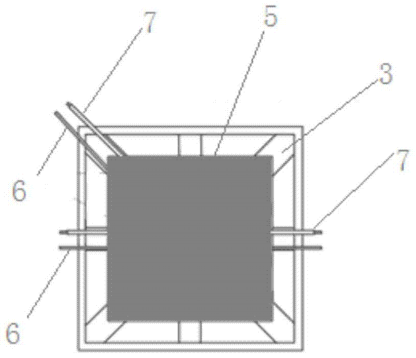
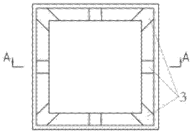
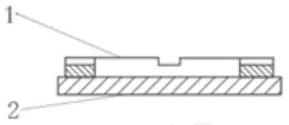
[0041] A test device for hot molding and curing deformation of resin-based composite materials, including resin-based composite material prepregs 5 laid in the mold and FBG sensors arranged in the middle, and multiple FBG sensors are laid in the same prepreg layup or Lay FBG sensors in multiple prepreg layers, lay FBG sensors along the fiber axis direction on the nth layer (n>1) as a strain sensor 6, and lay a reference sensor 7 for temperature compensation on the n+1th layer, The mold side wall frame plate is provided with a lead wire groove 3, and the surface of the mold side wall frame plate and the lead wire groove is covered with a high temperature resistant polymer film 4, and the lead wire of the sensor is drawn out from the lead wire groove 3 of the mold side wall frame plate 1. The signal receiver is switched on.

[0042] Preparation and use method:

[0043] (1) Process lead grooves with a width of 10mm and a depth of 1.5mm at the middle position of each side and at ...

Embodiment 2

[0053] A test device for hot molding and curing deformation of resin-based composite materials, including resin-based composite material prepregs 5 laid in the mold and FBG sensors arranged in the middle, and multiple FBG sensors are laid in the same prepreg layup or FBG sensors are respectively laid in multiple prepreg layups, FBG sensors are laid on the nth layer (n>1) along the direction of the fiber axis as strain sensors 6, and reference sensors 7 for temperature compensation are also laid on the nth layer. The side wall frame plate is provided with a lead groove 3, and the surface of the mold side wall frame plate and the lead groove is covered with a high temperature resistant polymer film 4, and the lead wire of the sensor is drawn out from the lead groove 3 of the mold side wall frame plate 1 to communicate with the signal. The receiver is switched on.

[0054] Preparation and use method:

[0055] (1) Process lead grooves with a width of 10 mm and a depth of 2.0 mm a...

Embodiment 3

[0065] A test device for hot molding and curing deformation of resin-based composite materials, including resin-based composite material prepregs 5 laid in the mold and FBG sensors arranged in the middle, and multiple FBG sensors are laid in the same prepreg layup or FBG sensors are respectively laid in multiple prepreg layups, FBG sensors are laid along the fiber axis direction on the nth layer (n>1) as strain sensors 6, and reference sensors 7 for temperature compensation are laid on the n-1th layer, The mold side wall frame plate is provided with a lead wire groove 3, and the surface of the mold side wall frame plate and the lead wire groove is covered with a high temperature resistant polymer film 4, and the lead wire of the sensor is drawn out from the lead wire groove 3 of the mold side wall frame plate 1. The signal receiver is switched on.

[0066] Preparation and use method:

[0067] (1) Process lead grooves with a width of 10 mm and a depth of 2.0 mm at the middle p...


PUM

PropertyMeasurementUnit
densityaaaaaaaaaa
thicknessaaaaaaaaaa

Abstract

The invention relates to a testing device for resin matrix composite material hot mold pressing curing deformation and a manufacturing and using method thereof. The testing device comprises resin matrix composite material prepreg and FBG sensors arranged in the prepreg. The method comprises the steps that the FBG sensors are laid on the nth layer in the fiber axial direction to be used as strain sensors, reference sensors for temperature compensation are laid on the nth layer or the (n+1)th layer or the (n-1)th layer, lead grooves are formed in a mold side wall frame board, the mold side wall frame board is coated with a high temperature resistance polymer film, leads of the sensors are led out of the lead grooves and connected with a signal receiver, a mold is closed, hot press molding is carried out, and curing forming on-line real-time monitoring is achieved. The problems that during composite material heat mold pressing curing deformation monitoring, grid regions are fragile and prone to breakage, and monitoring signals cannot be effectively transmitted if leading is inappropriate in a closed full-rigid hot mold pressing mold are solved, and meanwhile the problem that a composite material structure part with built-in FBG sensors is hard to break away from the full-rigid mold is solved.

Description

technical field [0001] The invention relates to an optical fiber Bragg grating test device for thermal molding and curing deformation of advanced resin-based composite materials and a method for detaching the composite material and the mold with a built-in fine sensor, in particular to a fiber-reinforced resin-based composite with pre-embedded optical fiber Bragg grating A test device for curing deformation of material structural parts in a hot molding manufacturing process, and a method for detaching from a composite material with an embedded fiber Bragg grating and a fully rigid closed mold. Background technique [0002] In recent years, fiber-reinforced resin-based composites have been widely used in aerospace, automobiles, ships, etc. Ships, construction and other fields are widely used. In particular, the density of the composite material is low, especially the density of the carbon fiber / resin composite material is only about 1.6g / cm 3 , far less than the density of ...

Claims


Application Information

Patent Timeline
Patent Type & Authority Patents(China)
IPC IPC(8): G01B11/16G01D3/036
Inventor 贾玉玺智杰颖董琪耿湘宜王静王海庆隋青美
Owner SHANDONG UNIV
Learn More