Eureka AIR delivers breakthrough ideas for toughest innovation challenges, trusted by R&D personnel around the world.

Control circuit of power MOSFET switching tube source electrode drive topological structure

A MOS tube and source drive technology is applied to the control circuit field of the power MOSFET switch tube source drive topology, which can solve the problems of unfavorable LED drive circuit design, high cost, and high loss of the drive circuit, and achieves a simple and reliable control method. Reduce volume and cost, optimize the effect of design

Active Publication Date: 2015-02-04
SUZHOU ORIENTAL SEMICONDUCTOR CO LTD
View PDF6 Cites 2 Cited by
  • Summary
  • Abstract
  • Description
  • Claims
  • Application Information

AI Technical Summary

Problems solved by technology

The flyback LED drive circuit has the following main disadvantages: first, the transformer has three windings, which is large in size and high in cost, which is not conducive to the design of the LED drive circuit built in the power supply; second, the loss of the drive circuit is high, resulting in low system efficiency; It is the power MOS tube that needs frequent switching actions and consumes a lot of energy
However, due to the use of two voltage sampling networks in the LED drive circuit, there are still the following obvious deficiencies: its circuit structure is complex, the chip area is large and the power consumption is high.

Method used


Image

  • Control circuit of power MOSFET switching tube source electrode drive topological structure
  • Control circuit of power MOSFET switching tube source electrode drive topological structure
  • Control circuit of power MOSFET switching tube source electrode drive topological structure

Examples


Embodiment Construction

[0023] The specific implementation manners of the present invention will be further described in detail below in conjunction with the drawings and examples.

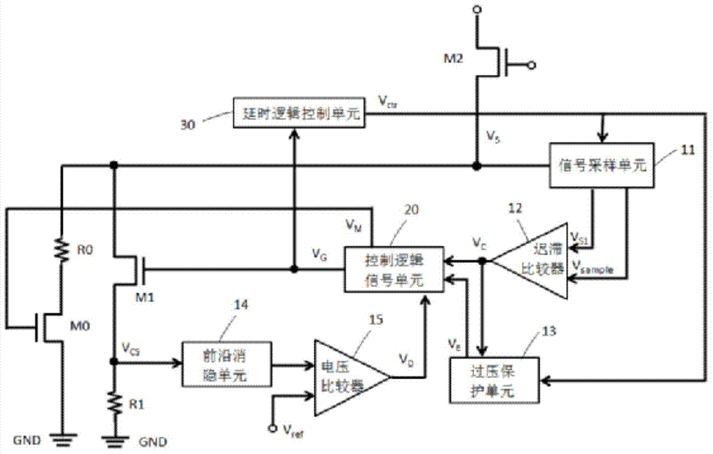
[0024] like image 3 As shown, a control circuit of a power MOSFET switch tube source drive topology proposed by the present invention includes a power MOSFE switch tube M2, a high-voltage switch MOS tube M1, a resistor R1, a delay logic control unit (30), and a signal sampling A unit (11), a hysteresis comparator (12), an overvoltage protection unit (13), a leading edge blanking unit (14), a voltage comparator (15) and a control logic signal unit (20).

[0025] The source of the power MOSFET switch M2 is connected to the drain of the high-voltage switch MOS transistor M1, and the gate and drain of the power MOSFET switch M2 are respectively connected to an external power supply voltage and a transformer or an inductor.

[0026] The source of the high-voltage switch MOS transistor M1 is connected to the circuit ground G...


PUM


Abstract

The invention belongs to an LED drive circuit and particularly relates to a control circuit of a power MOSFET switching tube source electrode drive topological structure. The control circuit includes a power MOSFET switching tube and a high-voltage switching MOS transistor which is connected with a circuit ground wire through a resistor. The control circuit also includes a time delay logic control circuit, a signal sampling unit, a leading edge blanking unit, a control logic signal unit, a voltage comparator, a hysteresis comparator and an overvoltage protection unit. The control circuit of the power MOSFET switching tube source electrode drive topological structure adopts a source electrode delay sampling technology so that the complexity and area of the LED drive control circuit can be reduced and the manufacturing cost is reduced. The control circuit of the power MOSFET switching tube source electrode drive topological structure also has the advantages of being simple in control method, easy to realize, low in power consumption and high in efficiency.

Description

technical field [0001] The invention belongs to the technical field of LED driving circuits, and in particular relates to a control circuit of a power MOSFET switching tube source driving topological structure. Background technique [0002] figure 1 is a simplified schematic diagram of a traditional flyback LED drive circuit, such as figure 1 As shown, the LED drive circuit includes a rectifier bridge, the alternating current AC is rectified by the AC bridge and filtered by the capacitor C1 to generate a DC voltage, that is, the bus voltage; the resistor R1 and the capacitor C2 form the chip starting branch; the primary winding of the transformer is connected to To the bus voltage and the drain of the power MOS transistor M0, the secondary winding is connected between the freewheeling diode D1 and the capacitor C3; the auxiliary winding is connected between the diode D2 and the circuit ground, when the circuit is working normally, it is mainly provided by the auxiliary wind...

Claims


Application Information

Patent Timeline
IPC IPC(8): H05B37/02
Inventor 王永寿王鹏飞龚轶刘伟苗跃
Owner SUZHOU ORIENTAL SEMICONDUCTOR CO LTD
Why Eureka
Eureka Blog
Learn More