Motion control method suitable for automatic welding of complex curve device

An automatic welding and motion control technology, applied in welding equipment, manufacturing tools, arc welding equipment, etc., can solve the problems of low quality, real-time control, and image data processing to reduce real-time performance, and achieve flexible and simple control and high degree of automation. Effect

Inactive Publication Date: 2015-02-18
JIEYANG SHUNXING STAINLESS STEEL IND +1
View PDF6 Cites 8 Cited by
  • Summary
  • Abstract
  • Description
  • Claims
  • Application Information

AI Technical Summary

Problems solved by technology

[0007] Manual welding has low production efficiency and low quality, which is likely to cause defects such as solder spots, burn-through, impermeable welding, and air holes in the welds; while ordinary automatic welding systems can improve production efficiency, they usually impose higher requirements on the control system hardware. Higher requirements, and need to be matched with complex software program control; and there are often processing and assembly errors in the devices or workpieces to be welded, it is difficult to solve these errors with the invariable welding trajectory given in advance, and it is also difficult to adapt to the welding heat process. deformation of
However, the existing automatic welding control schemes often have complicated software program control and huge data information processing, which can neither guarantee the quality of automatic welding nor perform real-time control according to the current welding situation.
Most of the current automatic welding control methods are based on image processing of welding arc light. However, since the arc light in the welding process is affected by many factors, such as welding position, welding material type, etc., the accuracy of arc light image processing will be greatly reduced. , and the huge image data processing also reduces the real-time performance of the control

Method used


Image

  • Motion control method suitable for automatic welding of complex curve device
  • Motion control method suitable for automatic welding of complex curve device
  • Motion control method suitable for automatic welding of complex curve device

Examples


Embodiment Construction

[0042] The following will clearly and completely describe the technical solutions in the embodiments of the present invention with reference to the drawings in the embodiments of the present invention. Apparently, the described embodiments are only some of the embodiments of the present invention, but not all of them. Based on the embodiments of the present invention, all other embodiments obtained by persons of ordinary skill in the art without creative efforts fall within the protection scope of the present invention.

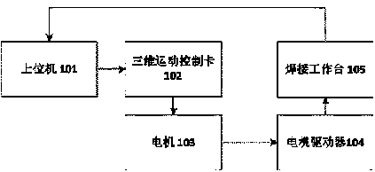
[0043] The motion control method suitable for automatic welding of complex curved devices provided by the embodiment of the present invention is based on a welding system including a host computer, a three-dimensional motion control card, a motor, and an automatic welding workbench.

[0044] see figure 1 , is a structural schematic diagram of an embodiment of the automatic welding system provided by the present invention.

[0045] During specific implementa...


PUM


Abstract

The invention discloses a motion control method suitable for automatic welding of a complex curve device. The motion control method comprises the following steps: a three-dimensional motion control card is plugged in a PCI bus interface of an upper computer, and is connected with an automatic welding bench through a motor; the three dimensional spatial structure of a to-be-welded device is simulated on the upper computer; a control instruction is sent to the three-dimensional motion control card according to the three dimensional spatial structure of the to-be-welded device; the three dimensional control card controls the working state of the motor according to the control instruction; the motor controls the welding bench to conduct linkage according to the predetermined motion of the three dimensional spatial structure of the to-be-welded device; the welding bench conducts automatic welding on the to-be-welded device, and feeds back current welding coordinate to the upper computer in a real-time manner. The motion control method is suitable for welding of a complex curve path, and has the advantages that the motion control method is low in cost, flexible to control, and high in work efficiency and automation degree.

Description

[0001] technical field [0002] The invention relates to the technical field of automatic processing, in particular to a motion control method suitable for automatic welding of devices with complex curves. [0003] Background technique [0004] As a very important manufacturing process, welding is widely used in machinery manufacturing, petrochemical, marine ships, bridge construction, metallurgy and mining, aerospace electronic information and other industrial sectors. Today, welding has developed into an independent discipline. [0005] In recent years, with the continuous rise of automation and intelligent manufacturing in various countries, research on the field of automatic processing has always been a research hotspot in various countries. With the development of microelectronics technology, digital signal processing technology and embedded systems related to various programming languages, the integration and reliability of motion control cards have been continuous...

Claims


Application Information

Patent Timeline
Patent Type & Authority Applications(China)
IPC IPC(8): B23K9/16B23K9/10
CPCB23K9/032B23K9/127B23K9/16
Inventor 郑旭生贺长林陈少克
Owner JIEYANG SHUNXING STAINLESS STEEL IND
Why Eureka
Try Eureka