Heat management system for electric locomotive traction converter

A traction converter and thermal management system technology, applied in the modification of power electronics, electrical components, output power conversion devices, etc., can solve the problem of air-cooled or water-cooled heat exchangers being large in size, unable to meet heat dissipation requirements, and device fatigue. Aging and other problems, to achieve the effect of low cost, rapid response, and improved device life

Active Publication Date: 2015-02-18
CSR ZHUZHOU ELECTRIC LOCOMOTIVE RES INST
View PDF7 Cites 9 Cited by
  • Summary
  • Abstract
  • Description
  • Claims
  • Application Information

AI Technical Summary

Problems solved by technology

At the same time, the cooling form and structure of the above structure also requires a huge external radiator to take away its heat
In the form of convective heat exchange, relying on the heat capacity of gas and liquid to take away heat, it has been unable to meet the heat dissipation requirements in some specific situations
In addition, in the existing cooling form, the working temperature of the cooled device will be affected by the heating power of different working conditions and the fluctuation of the ambient temperature, which is actually unstable. Under long-term temperature fluctuations, the device will fatigue due to thermal stress Ageing
Moreover, since the heat exchange area is related to the temperature difference and heat exchange efficiency, and the temperature difference should not be too large, the heat exchange efficiency has a limit, so the volume of the air-cooled or water-cooled heat exchanger is relatively large.

Method used


Image

  • Heat management system for electric locomotive traction converter
  • Heat management system for electric locomotive traction converter

Examples


Embodiment 1

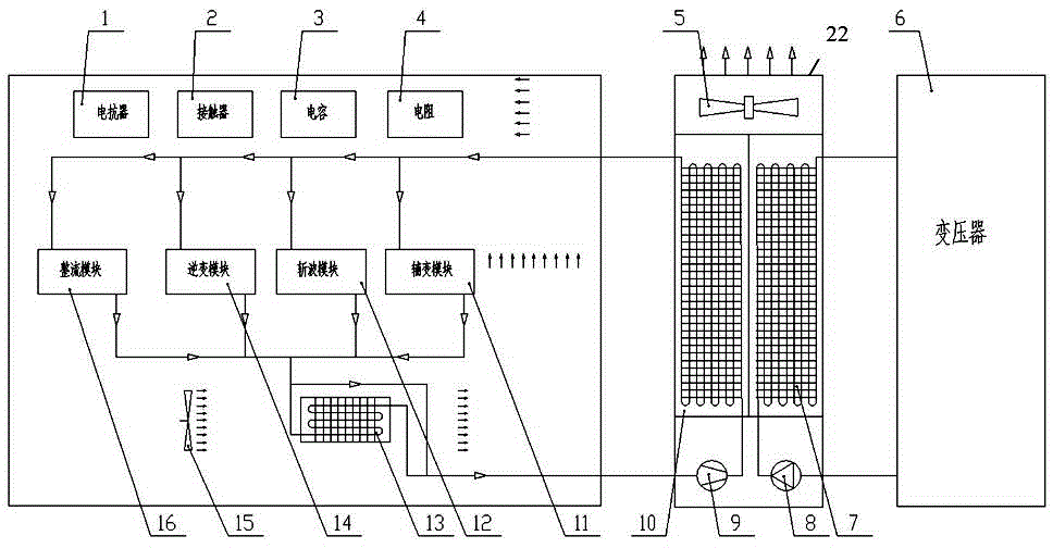
[0025] Embodiment 1: as figure 1 As shown, the thermal management system for the electric locomotive traction converter of the present invention includes a cooling tower 22, a compressor 9 and a condenser 10 installed in the cooling tower 22, and the cooling tower 22 is connected with the traction converter of the electric locomotive. converter cabinet together to form a complete system. Reactor 1, contactor 2, capacitor 3, resistor 4, auxiliary transformer module 11, chopper module 12, evaporator 13, inverter module 14, internal circulation fan 15 and rectifier module 16 are installed in the converter cabinet. The compressor 9 compresses the refrigerant in the system into high-temperature and high-pressure steam, and dissipates the heat of the system to the environment through the condenser 10; after the refrigerant becomes a normal temperature and high-pressure liquid, it is divided into two paths: one path enters the power device in the converter cabinet In the cooling dev...

Embodiment 2

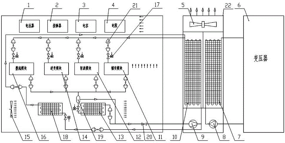
[0030] Embodiment 2: as figure 2 As shown, the thermal management system for the electric locomotive traction converter of the present invention includes a cooling tower 22, a compressor 9 and a condenser 10 installed in the cooling tower 22, and the cooling tower 22 is connected with the traction converter of the electric locomotive. converter cabinet together to form a complete system. Reactor 1, contactor 2, capacitor 3, resistor 4, auxiliary transformer module 11, chopper module 12, evaporator 13, gas-liquid separator 19, inverter module 14, internal circulation fan 15 are installed in the converter cabinet , The rectification module 16. The compressor 9 compresses the refrigerant in the system into high-temperature and high-pressure steam, and dissipates the heat of the system to the environment through the condenser 10; after the refrigerant becomes a normal temperature and high-pressure liquid, it is divided into two paths: one path enters the power device in the conv...


PUM


Abstract

The invention discloses heat management system for an electric locomotive traction converter. The heat management system comprises a cooling tower, an evaporator and an internal circulation draught fan. The cooling tower and a converter cabinet of the electric locomotive traction converter are connected into a whole. The evaporator and the internal circulation draught fan are installed in the converter cabinet. The cooling tower is provided with a compressor and a condenser. The compressor is connected with the condenser through a pipeline, refrigerant in the pipeline is compressed into high-temperature and high-voltage steam, and the heat is dissipated to the environment through the condenser. The refrigerant becomes high-temperature and high-voltage liquid and then is divided into two paths. One path of liquid enters a heat dissipation device of a power device in the converter cabinet and becomes a low-temperature and low-voltage gas-liquid mixing state to absorb heat. The other path of liquid enters the evaporator, and the internal circulation draught fan faces the evaporator so as to blow cold air into the converter cabinet. The heat management system has the advantages that the integral heat exchanging efficiency of the converter is improved, and the working temperature is reduced and is stable and is not affected easily by the outside environment.

Description

technical field [0001] The invention mainly relates to the field of rail transit vehicles, in particular to a heat management system suitable for traction converters of electric locomotives. Background technique [0002] In the application of modern high-power electric locomotives, with the increasing power of traction motors, the problem of heat dissipation of traction converters has become increasingly prominent, including high-power semiconductor devices such as IGBTs and diodes, as well as transformers, reactors, capacitors, etc. device. The above-mentioned devices generate a lot of heat, and the heat flux density of the actual heat dissipation is also increasing, but the maximum withstand temperature is limited, and the operating temperature and its fluctuations have a great impact on the life and reliability of power electronic devices; The passing current of some devices is also directly related. In this field, various heat dissipation technologies emerge in an endl...

Claims


Application Information

Patent Timeline
Patent Type & Authority Applications(China)
IPC IPC(8): H02M1/00H05K7/20
CPCH02M1/00H05K7/20909H05K7/20936
Inventor 冯江华胡家喜姚磊尚敬李彦涌黄华坤王翱岸
Owner CSR ZHUZHOU ELECTRIC LOCOMOTIVE RES INST
Why Eureka
Try Eureka