
Deep hole punching method and deep hole punch head thereof for large forging

A large forging and deep hole technology, applied in the field of forging, can solve the problems of complex machining process, stress concentration, long production cycle, etc., and achieve the goal of eliminating internal structure defects, reducing stamping force and homogenizing internal structure Effect

Active Publication Date: 2015-03-04
SHANGHAI XINMIN DONGTAI HEAVY FORGING
View PDF3 Cites 5 Cited by
  • Summary
  • Abstract
  • Description
  • Claims
  • Application Information

AI Technical Summary

Problems solved by technology

[0003] In the supercritical and ultra-supercritical unit systems, there are a large number of pipe fittings, tube sheets, straight tees, inclined tees, valve bodies and other pipe parts. The structural characteristics of these parts are large size, thick wall, and deep hole. In the harsh environment of high temperature and high pressure, and the sudden change of pressure caused by high variable load and pipeline eddy current impact, it is easy to cause uneven stress distribution or stress concentration, resulting in fatigue, creep damage, and even reduced parameter operation, affecting power generation efficiency , will bring security problems in severe cases
The use of heat-resistant alloy materials, such as P92, P122 or E911 steel, can improve the high temperature and high pressure resistance of tubular parts, but it cannot optimize the internal material structure of these large block parts, as well as physical properties such as coarse grains and cracks. Defects, the internal structure defects of these materials can only be overcome and optimized by post-processing technology
[0004] Although the forging process can significantly improve the internal structure of the part material and strengthen its mechanical properties, in the process of punching the deep hole of the forging, due to the large friction between the punch and the blank hole wall, and the impact of the hole wall on the punch rod Due to the tightening force of the punch and the negative pressure at the end of the punch, the punch cannot be pulled out from the blank after stamping. Therefore, it is difficult to realize deep hole processing through the stamping process for large block forgings at present. On the forged blank, deep hole cutting is carried out by machining methods such as drilling and boring. At present, this processing method has many shortcomings: first, the material utilization rate is low, and the chips generated during the machining process of the hole become waste and difficult to produce. Reuse, forming a great waste of high-quality alloy materials
Second, the cutting process cannot change the structure of the material around the hole wall, which is not conducive to enhancing the temperature and pressure resistance of the parts. Since large forgings are thick cake solid forgings, it is difficult to heat through and compact. There are differences in the thermodynamic and dynamic conditions of the core. There are defects such as segregation, porosity, and shrinkage cavity inside the billet, and the deep hole is often located in the core of the billet where cracks and coarse grains are the most serious. It is difficult to guarantee the axial mechanical properties of the tube hole during cutting. Consistency of performance
Third, the machining process is complicated and the production efficiency is low. Because the long diameter of the deep hole is relatively large, it needs to be drilled and then bored to the predetermined size during processing. Therefore, the workpiece needs to be transferred in multiple processes, the production cycle is long, and the efficiency Low

Method used


Image

  • Deep hole punching method and deep hole punch head thereof for large forging

Examples


Embodiment Construction

[0031] Take a straight-through pipe section of an ultra-supercritical generator set as an example. The finished straight-through pipe section has an outer diameter of 566mm, a length of 3200mm, a diameter of 302mm, a pipe wall thickness of 132mm, and a length-to-diameter ratio of the pipe hole of 10.6. Eight prism-shaped forged steel ingots are used, and the ingot material is martensitic heat-resistant steel P112.

[0032]Firstly, the steel ingot is heated in stages. First, the forged steel ingot is put into the heating furnace for heating, so as to improve the metal plasticity, make it easy to flow and form and obtain a good after-forging structure. Molded in a state of good plasticity. Since the steel ingot is a large piece, in order to reduce the temperature stress caused by the temperature difference of the section, the steel ingot should be heated and heated evenly. The present invention adopts the seven-stage heating and temperature rise specification. The temperature i...


PUM


Abstract

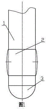
The invention discloses a deep hole punching method, which comprises the following steps of (1) heating a steel ingot; (2) discharging a forging blank, wherein the cutting amount of the head end is equal to the 16-20% of the weight of the steel ingot, and the cutting amount of the tail end is equal to the 8-12% of the weight of the steel ingot; (3) upsetting and drawing the forging blank, wherein the forging blank is upset and drawn to form a forging; (4) performing primary punching, wherein the press-down amount of a punch head is equal to 30% of the depth of a finished hole; (5) performing secondary punching, wherein the end of the punch head is applied with combustible matter and then is pressed down; (6) performing third punching, wherein the end of the punch head is applied with the combustible matter and then is pressed down; (7) trimming a hole; (8) performing heat treatment after forging. A deep hole punch head comprises a punch rod, wherein the punch rod is a cylindrical rod, the front end of the punch rod is a semispherical end, and a finishing ring is arranged on the punch rod, and is separated from the semispherical end. The deep hole punching method has the advantages that the production efficiency is high, the internal tissues are uniform and dense, and the utilization rate of materials is high. The deep hole punch head has the advantages that the structure design is skillful, the hole forming accuracy is high, and the quality is high.

Description

technical field [0001] The invention relates to the technical field of forging and forming, in particular to a process method for deep-hole stamping forming of large forgings in nuclear power or thermal power generating units. The invention also relates to a deep hole punch structure applied to the method. Background technique [0002] In the field of nuclear power and thermal power, in order to improve power generation efficiency and save power generation costs, more and more supercritical and ultra-supercritical generator sets are popularized and applied. Because the working fluid pressure of supercritical and ultra-supercritical units exceeds or far exceeds the critical pressure and temperature of the working fluid, the supercritical and ultra-supercritical units are in a state of high parameter and high pressure operation, which is very important for the unit department, especially the large number of units. Higher performance requirements such as temperature resistance...

Claims


Application Information

Patent Timeline
IPC IPC(8): B23P15/00B21D28/34
CPCB21D28/34B23P15/00
Inventor 王兴中王元华马武江
Owner SHANGHAI XINMIN DONGTAI HEAVY FORGING
Learn More