Preparation method of composite thin-walled shell based on unloading holes

A technology of thin-walled shells and composite materials, which is applied in the field of preparation of composite thin-walled shells, can solve the problems of easy deformation of thin-walled shells, and achieve the effects of small deformation, short production cycle and good applicability

Active Publication Date: 2017-10-24
BEIJING AEROSPACE HEZHONG TECH DEV +1
View PDF2 Cites 0 Cited by
  • Summary
  • Abstract
  • Description
  • Claims
  • Application Information

AI Technical Summary

Problems solved by technology

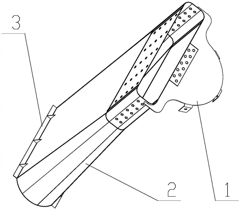
[0004] The purpose of the present invention is to solve the problem of easy deformation of the thin-walled shell of fiber-reinforced resin-based composite material used in space remote sensors, and propose a method for adding unloading holes. The thin-walled shell of fiber-reinforced resin-based composite material prepared by this method is not easily deformed, and can Ensure the surface-to-obstruction ratio, modulation transfer function (MTF) and stray light coefficient of the space remote sensor, while simplifying the structural design and molding process

Method used


Image

  • Preparation method of composite thin-walled shell based on unloading holes
  • Preparation method of composite thin-walled shell based on unloading holes
  • Preparation method of composite thin-walled shell based on unloading holes

Examples


Embodiment 1

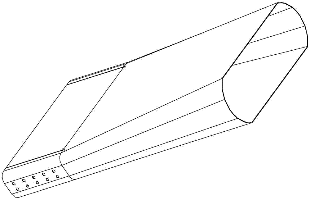
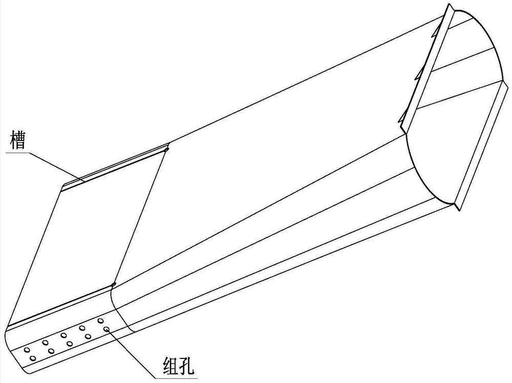
[0043] The cover body 2 adopts a prefabricated unloading hole method, which greatly simplifies the structural form of the inner cover, effectively controls its maximum deformation, and eliminates the reinforcement ribs 3 at the distal end of the cover body 2 at the same time. The structure diagram of the cover body 2 after adding the unloading hole is as follows: Figure 5 Shown.

[0044] 1 Design and manufacture the forming mold of the cover body 2. The mold is a male mold, and the mold is made of metal material. The shape of the mold is consistent with the inner cavity of the cover body 2. Before use, apply a layer of fluorocarbon release agent on the working surface of the mold. And air-dry; the fluorocarbon release agent can be replaced by other release agents with a temperature resistance of not less than 140°C; if necessary, the mold can be heated to 50-60°C.

[0045] 2 Prepare Kevlar49 / 8D-1 plain weave fabric prepreg with a nominal thickness of 0.1mm. The resin content of t...

Embodiment 2

[0052] The cover 2 adopts a post-processing unloading hole method, which greatly simplifies the structure of the inner cover, effectively controls its maximum deformation, and eliminates the reinforcement ribs 3 at the distal end of the cover 2 at the same time. The structure diagram of the cover body 2 after adding the unloading hole is as follows: Figure 5 Shown.

[0053] 1 Design and manufacture the forming mold of the cover body 2. The mold is a male mold, and the mold is made of metal material. The shape of the mold is consistent with the inner cavity of the cover body 2. Before use, apply a layer of fluorocarbon release agent on the working surface of the mold. And air-dry; the fluorocarbon release agent can be replaced by other release agents with a temperature resistance of not less than 140°C; if necessary, the mold can be heated to 50-60°C.

[0054] 2 Prepare Kevlar49 / 8D-1 plain weave fabric prepreg with a nominal thickness of 0.1mm. The resin content of the prepreg is ...


PUM


Abstract

The invention relates to a composite material thin-wall housing preparation method based on an unloading hole, and belongs to the technical field of composite material structure design and composite material processing technology. A composite material thin-wall housing prepared by using the preparation method is small in deformation, and has the maximum deformation of 0.5 mm or less under the room temperature condition, and the maximum deformation not exceeding 0.5 mm is of great importance to guarantee surface obstruction ratio, modulation transfer function (MTF) and veiling glare index of a space remote sensing system. The composite material thin-wall housing is simple in structural form, tedious structures such as ribs and the like are saved, and also structure weight is mitigated. The composite material thin-wall housing is high in technology maturity, simple in tools and molds, relatively good in adaptability to curing equipment and short in production period.

Description

Technical field [0001] The invention relates to a method for preparing a composite material thin-walled shell based on an unloading hole, and belongs to the field of composite material structure design and composite material processing technology. Background technique [0002] Advanced composite materials (ACM) have the advantages of light weight, high specific strength and specific modulus, fatigue resistance, good damping and shock absorption performance, and designable performance. They are gradually replacing the original metal materials as the key material for the structure of space remote sensors. In terms of process maturity and practical application range, resin-based composite materials with high-performance fibers as reinforcement have become important materials for the structure of space remote sensors, while carbon fiber composite materials (CFRP) and aramid fiber composite materials (AFRP) have Occupy the leading position among them. [0003] Some spatial remote senso...

Claims


Application Information

Patent Timeline
Patent Type & Authority Patents(China)
IPC IPC(8): B29C70/34
CPCB29C70/342
Inventor 章令晖陈萍
Owner BEIJING AEROSPACE HEZHONG TECH DEV
Why Eureka
Try Eureka