
Advanced control method for direct-current boost converter system

A technology of DC boost and control method, which is applied in the direction of converting DC power input to DC power output, control/regulation systems, instruments, etc., which can solve the problem that it is difficult for closed-loop systems to achieve fast and high-precision voltage output performance, and it is difficult to quickly track Given voltage, voltage input changes and other issues, to improve the anti-disturbance performance and tracking performance, good application value, and the effect of suppressing disturbances

Active Publication Date: 2015-03-04
SOUTHEAST UNIV
View PDF5 Cites 20 Cited by
  • Summary
  • Abstract
  • Description
  • Claims
  • Application Information

AI Technical Summary

Problems solved by technology

[0004] In the actual DC power supply equipment, most of the DC converter systems require high accuracy of the output voltage and the ability to quickly adapt to various working conditions. In some cases, for example, in the case of disturbances, integration is mainly used to eliminate the influence of disturbances on the output voltage, which is a passive and slow control method, especially when the system encounters fast time-varying or periodic It is difficult to quickly track the given voltage during disturbances, which mainly include load fluctuations, voltage input changes, etc.
If the controller does not quickly and actively deal with these disturbances, it is difficult for the closed-loop system to achieve fast and high-precision voltage output performance

Method used


Image

  • Advanced control method for direct-current boost converter system
  • Advanced control method for direct-current boost converter system
  • Advanced control method for direct-current boost converter system

Examples


Embodiment Construction

[0025] The embodiments of the present invention will be described in detail below with reference to the accompanying drawings: this embodiment is implemented under the premise of the technical solution of the invention, and detailed implementation methods and specific implementation processes are given, but the protection scope of the present invention is not limited to the following examples .

[0026] step one:

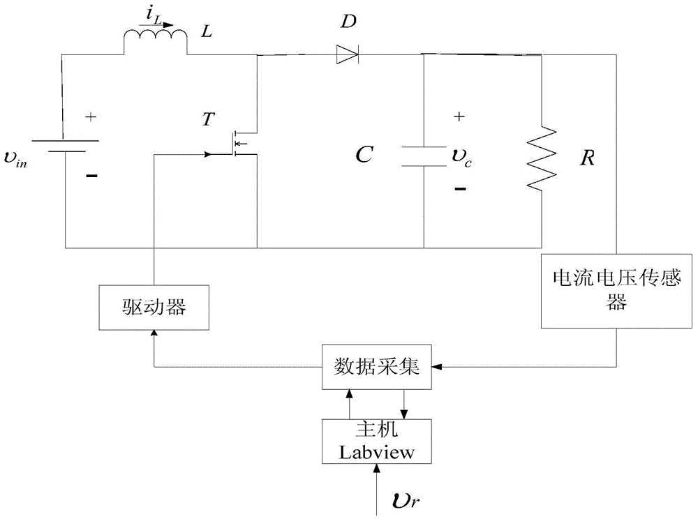
[0027] Such as figure 1 Show the structure diagram, establish a basic structure diagram of a DC boost converter, υ in Is the input voltage, L is the input inductance, i L Is the inductor current, D is the diode, T is the switch tube, C is the output capacitance, R is the load resistance, u is the control input of the switch tube T, that is, the controller output, υ c To output voltage, use current and voltage sensors to collect output voltage and inductor current signals, feed them back to DAQ board, perform control algorithm calculations in the host computer LabVIEW to ...


PUM


Abstract

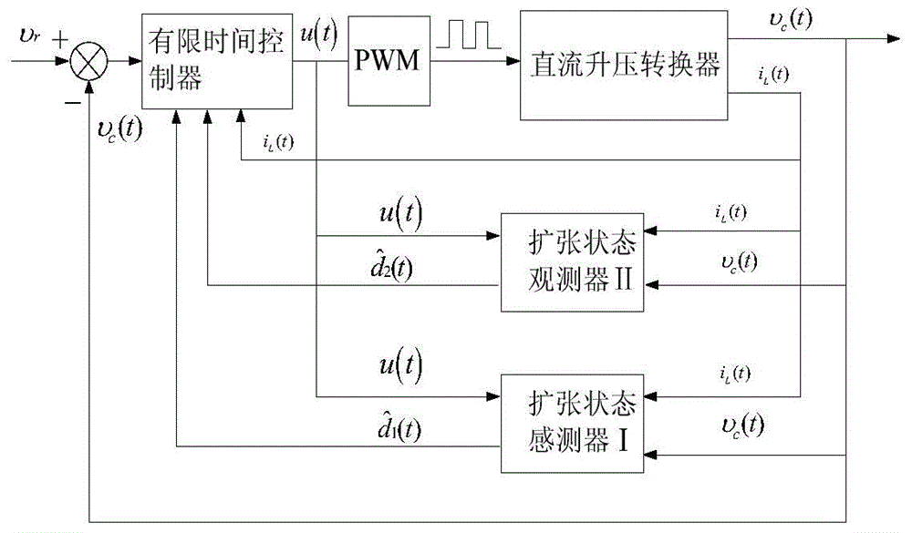
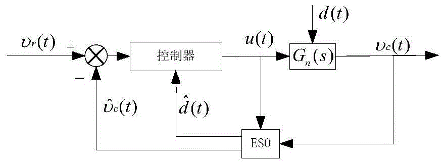
The invention discloses an advanced control method for direct-current boost converter system, applicable to high precision control of the direct-current boost converter system. The method adopts a current tracking mode based on extended state observers and a limit time control technology, and specifically includes the steps of: firstly, respectively observing disturbance of voltage change and resistive load by designing two extended state observers, based on the above, designing the limit time controller, and thereby obtaining a composite controller to control the direct-current boost converter system such that the direct-current boost converter system can quickly track target voltage with high precision under the presence of voltage change and resistive load disturbance. The method is simple to implement and relatively less in parameter adjustment, not only can improve the tracking speed of the direct-current boost converter system for reference signals, but also can effectively reduce steady-state wave motion of the power electronic direct-current boost converter and meet the application of high-performance power electronic direct-current boost converter systems.

Description

Technical field [0001] The invention relates to a power electronic DC boost converter system, in particular to a DC boost converter system control method based on an extended state observer and a limited time control technology. Background technique [0002] With the rapid development of modern science and technology, especially the great progress of power electronic technology, microelectronic technology, digital control technology and modern control theory, it has created favorable conditions for the development of power electronic DC switching power supply system, especially in robots and precision Radar, military weapons, new energy photovoltaic systems and other fields that require higher and higher control performance of DC switching power supplies, DC converter systems have received more and more attention. [0003] At present, the DC boost power electronic converter system mostly adopts a double closed loop control structure, that is, the inner loop is a current control loo...

Claims


Application Information

Patent Timeline
IPC IPC(8): H02M3/155
CPCH02M3/155
Inventor 李世华王军晓王佐樊静雯吴斌崔宏宇李奇
Owner SOUTHEAST UNIV
Learn More