Method for modifying thermal power station by storing energy through fused salt and device of method

A thermal power station and molten salt technology, applied in the field of solar thermal power generation and energy storage, can solve the problems of urban heating pipe network that consume a lot of manpower, material and financial resources, achieve rational use of energy, solve environmental problems, and solve the problem of excessive steam transmission distance big effect

Inactive Publication Date: 2015-03-11
江苏太阳宝新能源有限公司
5 Cites 7 Cited by

AI-Extracted Technical Summary

Problems solved by technology

[0003] Therefore, the thermal power stations in the urban area and the suburbs are facing closure, and the newly built thermal power stat...

Abstract

The invention relates to a method for modifying a thermal power station by storing energy through fused salt and a device of the method. A fused salt heat storage system and a steam generation system are adopted instead of a coal-fired boiler of the conventional thermal power station; the fused salt is heated by using off-peak electricity to store heat; the stored heat is transformed into high-temperature and high-pressure steam; power is generated on a power consumption peak, or regional heating is performed by using an original pipeline. By adopting the method and the device, environmental problems caused by coal burning of the conventional thermal power station are solved fundamentally, the carbon emission is reduced, the problem of overlarge steam conveying distance during heating of a newly-built remote thermal power plant can be solved, and the investment cost is saved. Meanwhile, the off-peak electricity can be utilized effectively, and reasonable utilization of energy is realized.

Application Domain

Technology Topic

Image

  • Method for modifying thermal power station by storing energy through fused salt and device of method

Examples

  • Experimental program(1)

Example Embodiment

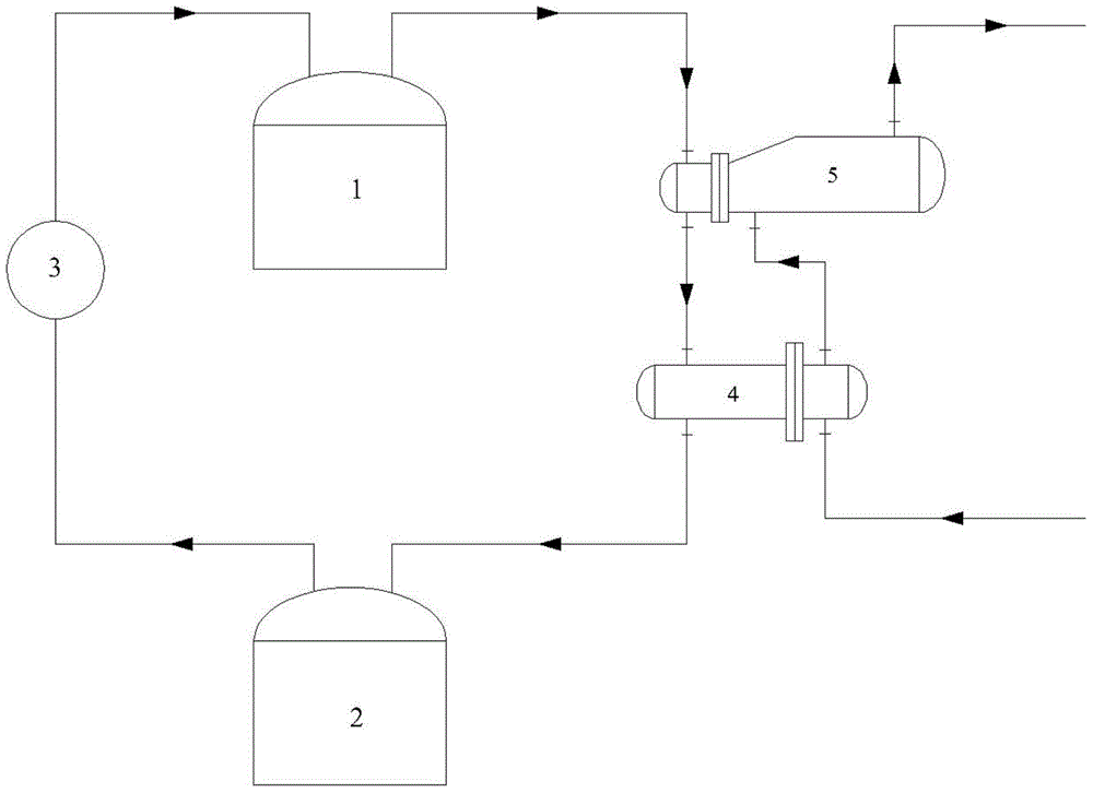
[0016] The present invention will now be described in further detail in conjunction with the accompanying drawings and preferred embodiments. These drawings are all simplified schematic diagrams, which only illustrate the basic structure of the present invention in a schematic manner, so they only show the configurations related to the present invention.
[0017] like figure 1 Shown is the device used in the method of using molten salt energy storage for thermal power station transformation, including molten salt heat storage system and steam generation system. The molten salt heat storage system is composed of a high-temperature molten salt tank 1, a low-temperature molten salt tank 2, and an electrically heated molten salt tank (furnace) 3; the steam generation system is composed of a preheater 4 and a steam generator 5.
[0018] figure 1 Among them, the electric heating molten salt tank/furnace is set between the high and low temperature molten salt tanks to heat the low temperature molten salt into high temperature molten salt; the high temperature molten salt tank is connected to the inlet of the steam generator, and the outlet of the steam generator is connected to the preheating The inlet of the preheater; the outlet of the preheater is connected to the low-temperature molten salt tank; the steam generator is also provided with a water inlet and a steam outlet; the water inlet of the steam generator is connected to the water outlet of the preheater; the steam outlet is connected to an external turbo generator; The water inlet of the preheater is connected with an external water source device.
[0019] The electric heating molten salt tank/furnace 3 uses low valley electricity to heat the molten salt in the low temperature molten salt tank 2 to 500°C, and stores it in the high temperature molten salt tank 1 . During the peak period of electricity consumption, the molten salt in the high-temperature molten salt tank 1 passes through the steam generator 5 and the preheater 4 in sequence, and the water in the steam generator 5 is heated into saturated steam, and the saturated steam is heated and then input into the turbogenerator for heating. generate electricity.
[0020] The high-temperature molten salt that does not produce saturated steam with the water in the steam generator enters the preheater through the pipeline, and the cooled molten salt is stored in the low-temperature molten salt tank 2 . The water in the preheater 4 is provided by an external water source device.
[0021] figure 1 Among them, the left end of the steam generator is set to the inlet and outlet respectively; the right end of the steam generator is set to the water inlet and steam outlet respectively; the left end of the preheater is set to the inlet and outlet respectively; the right end of the preheater is set to the water inlet respectively. and outlet.
[0022] In addition, the saturated steam generated by heating with high-temperature molten salt can use the original heating pipe network of the power station for regional heating, reducing investment.
[0023] What is described in the above description is only the specific implementation of the present invention, and various illustrations do not limit the essence of the present invention. Those of ordinary skill in the art can modify or modify the previous specific implementation after reading the description. variations without departing from the spirit and scope of the invention.

PUM

no PUM

Description & Claims & Application Information

We can also present the details of the Description, Claims and Application information to help users get a comprehensive understanding of the technical details of the patent, such as background art, summary of invention, brief description of drawings, description of embodiments, and other original content. On the other hand, users can also determine the specific scope of protection of the technology through the list of claims; as well as understand the changes in the life cycle of the technology with the presentation of the patent timeline. Login to view more.

Similar technology patents

Sodium bicarbonate dry method desulfurization ash resourceful treatment method

InactiveCN110697738ASolve environmental problemsAlkali metal sulfite/sulfate purificationEnvironmental chemistrySodium bicarbonate
Owner:南京金瀚环保科技有限公司

Classification and recommendation of technical efficacy words

  • Solve environmental problems
  • Reduce carbon emissions

Method for preparing potassium fluoride by utilizing potassium fluosilicate

ActiveCN103121699ASolve development and utilization problemsSolve environmental problemsAlkali metal fluoridesChemistryDecomposition
Owner:KINGENTA NORSTERRA CHEM CO LTD
Why Eureka
Try Eureka