A mems thermal flow sensor and its manufacturing method

A thermal flow sensor technology, applied in the field of sensing, can solve the problems of thermal flow sensor being easily polluted, anti-vibration and heat insulation incompatibility, etc., to ensure heat insulation and anti-vibration performance, and ensure measurement Accuracy and sensitivity, effects of preventing contamination and corrosion

Active Publication Date: 2018-04-10
BEIJING MXTRONICS CORP +1
View PDF8 Cites 0 Cited by
  • Summary
  • Abstract
  • Description
  • Claims
  • Application Information

AI Technical Summary

Problems solved by technology

[0003] The technical problem of the present invention is: to overcome the deficiencies of the prior art, to provide a MEMS thermal flow sensor and its manufacturing method, the thermal flow sensor solves the problem that the existing thermal flow sensor is easy to be polluted, anti-vibration and heat insulation The problem of incompatibility, the manufacturing method is simple, the cost is low, and mass production can be realized

Method used


Image

  • A mems thermal flow sensor and its manufacturing method
  • A mems thermal flow sensor and its manufacturing method
  • A mems thermal flow sensor and its manufacturing method

Examples


Embodiment Construction

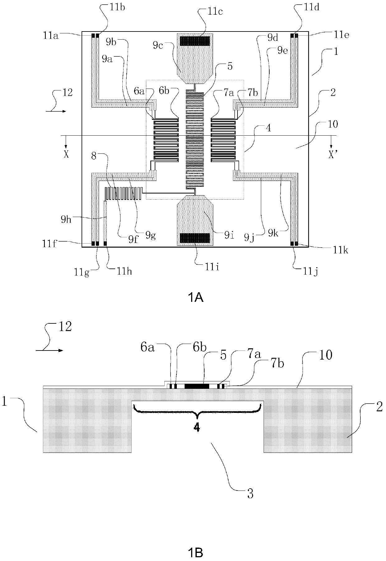
[0032] figure 1 It is a structural schematic diagram of MEMS thermal flow sensor of the present invention, 1A is its top view, and 1B is its edge view. figure 1 Sectional view of line X-X' of A.

[0033] MEMS thermal flow sensor 1, its structure includes a substrate 2, a cavity 3 is arranged at the bottom of the substrate 2, the substrate above the cavity 3 forms a thin film layer 4; the upper surface of the thin film layer 4 has a heating resistor 5, and the heating Resistor 5 is perpendicular to the direction of fluid movement, heating and controlling heating resistor 5 to make its temperature higher than that of fluid 12; both sides of heating resistor 5 are symmetrically arranged with a first group of thermistors along the direction of fluid movement and the second group of thermistor bodies, wherein the first group of thermistor bodies includes the first thermistor body 6a and the second thermistor body 6b, and the second group of thermistor bodies includes the third the...


PUM


Abstract

The invention discloses a MEMS thermal flow sensor and a manufacturing method thereof, wherein the MEMS thermal flow sensor comprises a substrate, a first group of thermistor bodies, a heating resistor body, a second group of thermistor bodies, and an ambient temperature measuring resistor Body, lead wire, passivation protection layer and electrode pad. The manufacturing method of the MEMS thermal flow sensor selects a material with insulation, high thermal resistance, and vibration resistance as the substrate, and sputters a metal layer or a semiconductor layer on the substrate, and forms a second layer by etching on the metal layer or semiconductor layer. A set of thermistor body, heating resistor body, the second group of thermistor body, ambient temperature measuring resistor body, lead wire, and passivation protective layer formed by silicon dioxide or polyimide at the same time, and electroplated at the end of the lead wire Gold or aluminum forms the electrode pad portion. The invention simplifies the processing technology, reduces the manufacturing cost, manufactures the spare thermistor body and the passivation protection layer, and improves the reliability of the sensor.

Description

technical field [0001] The invention relates to a microelectromechanical system (MEMS) thermal flow sensor and a manufacturing method thereof, belonging to the field of sensing technology. Background technique [0002] With the rapid development of science and technology and the continuous progress of science and technology, the task of flow detection is becoming more and more heavy. Due to the disadvantages of low sensitivity, large volume and high cost of traditional fluid sensors, there are great problems in the measurement of fluid characteristics of microfluids. limitation. With the continuous advancement of micro-electro-mechanical systems (MEMS) technology, MEMS flow sensors with the characteristics of small size and low power consumption have emerged as the times require, and are widely used in automobiles, natural gas, analytical chemistry, bioengineering, medical engineering, etc. . The thermal flow sensor measures a wide flow range, has high sensitivity, and has...

Claims


Application Information

Patent Timeline
Patent Type & Authority Patents(China)
IPC IPC(8): G01F1/69
Inventor 赵元富李光北张富强杨静孟美玉孙俊敏
Owner BEIJING MXTRONICS CORP
Why Eureka
Try Eureka