Oil-containing sludge resourceful treatment technology

A treatment process and resource utilization technology, applied in the sludge dehydration of oily sludge and crude oil recovery treatment process, can solve the problems of high cost, complicated process operation and unfavorable practical application of three-phase decanter centrifuges, and achieve improved crushing efficiency. Milky effect, excellent biodegradability, good dehydration effect

Active Publication Date: 2015-03-18
CHINA PETROLEUM & CHEM CORP +1
View PDF8 Cites 7 Cited by
  • Summary
  • Abstract
  • Description
  • Claims
  • Application Information

AI Technical Summary

Problems solved by technology

The process is relatively complicated, and the oil recovery rate needs to be improved
CN102092907A discloses a method for resourceful treatment of oily sludge. First, the emulsified water rich in sludge is removed by electrochemical methods, so that the sewage can meet the requirements of reinjection. After the treatment by this method, the water content of the oily sludge is reduced to less than 1% , in recovering a large amount of aged crude oil from the oily sludge, the aged oil contained in the oily sludge is reduced to less than 1% after being treated by this method, and finally the oily sludge is organically treated, and the oily sludge is organically treated by microbial fermentation , to achieve harmless discharge, and the final waste oil content is less than 3%, but the process is complicated to operate and high in cost, which is not conducive to practical application
CN102041038A discloses a treatment method for heavy oil aging oil, which solves the problem of demulsification and dehydration of heavy oil aging oil in the oilfield by using a demulsifier combined with centrifugation to treat the aging oil, but the three-phase decanter centrifuge used in the invention The cost of the machine is high, and the treatment effect on impurities lighter than water such as foam in sewage is relatively poor, which is not conducive to the treatment of sludge with high oil content

Method used


Image

  • Oil-containing sludge resourceful treatment technology
  • Oil-containing sludge resourceful treatment technology
  • Oil-containing sludge resourceful treatment technology

Examples


Embodiment 1

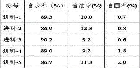
[0034] The concrete embodiment of the present invention is illustrated by taking the oil sludge at the bottom of a refinery as an example. The oily sludge content analysis of the feed is shown in Table 1. The weight percentages of the components of the demulsifier are: sodium lauryl alcohol ether carboxylate 15wt%, sodium silicate 20wt%, sodium chloride 2wt%, sodium hydroxide 1wt% , Water 62wt%, demulsifier dosage is 3% of sludge weight. The mixing time of the demulsifier in the sludge mixing tank is 30 minutes, and the temperature of the mixing tank is controlled at about 60°C. Using the process of the present invention to treat oily sludge, the water content of the discharged mud cake is reduced to 51.1%-54.9%, and the oil content is 16.9%-22.3%, as shown in Table 2. Through material balance calculation, the volume of sludge after dehydration treatment is reduced by at least 10 times, which greatly reduces the difficulty of subsequent sludge treatment. The contents of chem...


PUM


Abstract

The invention discloses an oil-containing sludge resourceful treatment technology, which comprises the following steps: oil-containing sludge in a raw material sludge storage pond is introduced in a sludge mixing tank for demulsification treatment, the oil-containing sludge after demulsification is introduced in a spiral sludge dewatering machine for solid-liquid separation to obtain a filtrate and mud cakes, the filtrate is introduced in a gas-liquid mixing tank for mixing with air, a mixture is introduced in a separation tank for oil, water and mud three-phase separating. According to the technology, water content of the oil-containing sludge is decreased from 80-98% to about 50%, most crude oil in the oil-containing sludge can be recovered, and subsequent processing difficulty of sludge can be greatly reduced. The technology has the advantages of wide application scope, and is especially suitable for treatment of oil sludge at bottom of pot, scum and activated sludge, and can be used for treating various kinds of oil-containing sludge generated by petroleum exploitation, storage and transportation enterprises.

Description

technical field [0001] The invention relates to a resource treatment process of oily sludge, in particular to a sludge dehydration and crude oil recovery treatment process of oily sludge. Background technique [0002] A large amount of black solid and semi-solid waste containing oil will be produced in the process of oil exploitation, gathering and transportation, refining and oily sewage treatment, which is called oil sludge, and its main components are crude oil, mud and water. The size of solid particles in oil sludge can range from less than microns to several inches, most of which are between 1 and 100 microns. The composition of oil depends on the type of crude oil, refinery structure and operating conditions. The composition of sludge may change over time. According to statistics, China's annual output of oil sludge is nearly 3 million tons, which contains about 600,000 tons of crude oil resources. In addition to a large amount of aged crude oil, waxy, and colloidal ...

Claims


Application Information

Patent Timeline
Patent Type & Authority Applications(China)
IPC IPC(8): C02F11/00C02F11/12
CPCC02F1/24C02F1/40C02F11/00C02F11/121C02F2303/06C10G1/00C10G2300/1003
Inventor 杨飞飞回军李宝忠赵景霞
Owner CHINA PETROLEUM & CHEM CORP
Why Eureka
Try Eureka