
Method for intensifying selective decomposition of zinc ferrite

A selective, zinc ferrite technology, applied in the fields of mineral processing and metallurgical engineering, can solve problems such as inability to guarantee at the same time, high decomposition rate, etc., and achieve the effect of mild conditions, wide temperature range, and favorable industrial production

Active Publication Date: 2015-03-25
CENT SOUTH UNIV
View PDF4 Cites 10 Cited by
  • Summary
  • Abstract
  • Description
  • Claims
  • Application Information

AI Technical Summary

Problems solved by technology

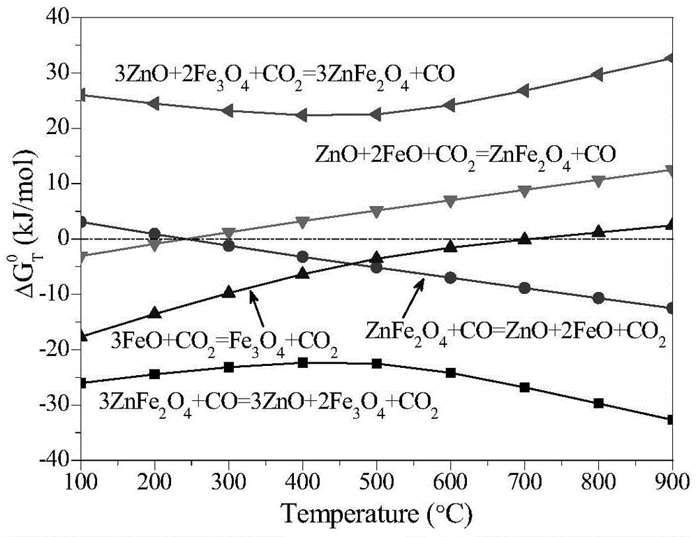
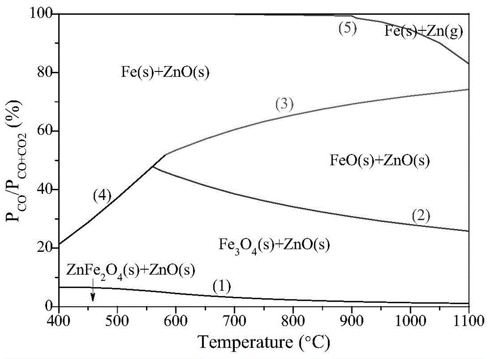
[0003] Aiming at the defect that the process for processing zinc ferrite in the prior art cannot guarantee a high decomposition rate and a good magnetization effect at the same time, the purpose of the present invention is to provide a method that can not only ensure the full decomposition of zinc ferrite, but also inhibit the A roasting method of phase overreduction to ferrous oxide, which provides reliable technical support for the popularization and application of the new process of selective decomposition of zinc ferrite

Method used


Image

  • Method for intensifying selective decomposition of zinc ferrite
  • Method for intensifying selective decomposition of zinc ferrite

Examples


Embodiment 1

[0030] Zinc calcine with higher zinc ferrite content is used as raw material, the zinc content of the zinc calcine is 57.4%, the iron content is 13.3%, and the iron content in the zinc ferrite accounts for 82.5% of the total iron content. Grind the zinc calcine to be below -75μm, dry it, put it into a small closed rotary kiln in the laboratory, raise the temperature to about 800°C under the condition of nitrogen protection, then stop feeding nitrogen, and feed CO and CO at the same time 2 and mixed gas, so that the total gas flow is controlled at about 1.25L / min, P CO / P (CO+CO2) Control it at about 40%, after reduction roasting for 1.5h, stop heating, lower the temperature in the roasting furnace to about 550°C, keep the temperature constant, and then adjust the roasting atmosphere to ensure the P of the atmosphere. CO / P( CO + CO2 ) is controlled within 5%, after magnetization roasting for 1h, turn off the heating furnace, stop feeding CO and CO 2 Gas, naturally cooled t...

Embodiment 2

[0036] The test uses the zinc leaching slag produced in the conventional hydrometallurgy process as the raw material. The leaching slag has a zinc content of 19.6%, an iron content of 23.9%, and is mainly composed of zinc ferrite. Grind the zinc leaching slag to be below -75μm, dry it, put it into a small closed rotary kiln in the laboratory, raise the temperature to about 750°C under the condition of nitrogen protection, then stop feeding nitrogen, and feed CO and CO at the same time 2 and mixed gas, so that the total gas flow is controlled at about 1.25L / min, P CO / P (CO+CO2) Control it at about 45%. After reduction roasting for 75 minutes, stop heating, lower the temperature in the roasting furnace to about 550°C, keep the temperature constant, and then adjust the roasting atmosphere to ensure the P of the atmosphere. CO / P( CO + CO2 ) within 5%, after 30 minutes of magnetization roasting, turn off the heating furnace, and stop feeding CO and CO 2 The gas was naturally ...


PUM


Abstract

The invention discloses a method for intensifying selective decomposition of zinc ferrite. The method comprises the following steps: putting a zinc ferrite material into a roasting furnace, adjusting the atmosphere inside the roasting furnace to reduction atmosphere, performing reduction roasting at high temperature firstly, further reducing the reduction property of the atmosphere of the roasting furnace, reducing the temperature of the roasting furnace for magnetic roasting, and after the magnetic roasting is completed, recycling iron and zinc by using an acid leaching and magnetic separation method. By adopting the method, not only is the selective decomposition of zinc ferrite intensified, but also the decomposition rate of the zinc ferrite is increased, the magnetization effect of iron phase is improved, the roasting condition range is greatly enlarged, the operation is simplified, and the industrialization application is promoted.

Description

technical field [0001] The invention relates to an economical and easily realized method for selectively decomposing zinc ferrite, which belongs to the field of mineral processing and metallurgical engineering. Background technique [0002] More than 80% of the world's zinc metal is produced in conventional wet zinc smelting plants, and its main process is oxidation roasting-leaching-purification-electrowinning. Zinc ferrite is an inevitable by-product in the process of zinc hydrometallurgy. It has a stable structure and is insoluble in weak acid and weak alkali solutions. It is difficult to dissolve zinc ferrite in conventional neutral leaching and low acid leaching, resulting in a large amount of zinc ferrite as The main leaching slag is produced. It is estimated that every 10,000 tons of electrolytic zinc will produce 9,600 tons of leaching slag, and the leaching slag contains a large amount of heavy metal elements, such as Zn, Fe, Pb, Ag, In, Ga, etc. The stockpiling of...

Claims


Application Information

Patent Timeline
IPC IPC(8): C22B1/02
CPCC22B1/02
Inventor 刘维覃文庆韩俊伟
Owner CENT SOUTH UNIV
Learn More